By T.K. Hareendran, contributing editor
Many different vendors offer development boards, but the boards often offer only basic resources, requiring the purchase of additional modules to build out a project. Jailbreaking a standalone module intended for another purpose, however, can yield a development platform richer with resources for much less cost. Programmable countdown timers offer one such opportunity.
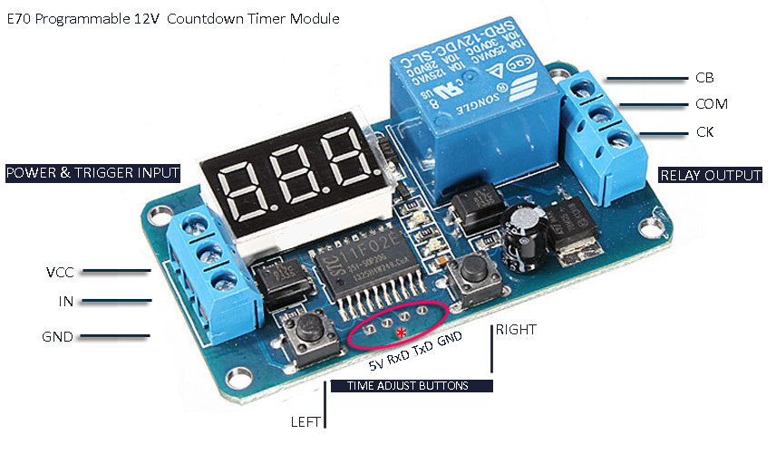
I love microcontrollers. To me, “hackable” microcontroller modules help to hasten the initial designing/prototyping process of new projects. I’ve been tinkering with a number of cheap Chinese electronics modules recently, and right now, the “E70 countdown timer module” from Deek Science and Technology Ltd. is my favorite target. It’s a compact, programmable, digital countdown timer with an onboard STC11F02E microcontroller, three-digit LED display, and electromagnetic relay. There’s also an onboard voltage regulator chip, two tactile switches, and two status indicators. Other features in the list are power-down (non-volatile) memory retention and external trigger input with galvanic isolation.
What’s quite interesting is that, just near the chip, the module also has a set of pinouts providing what looks like an in-system programming (ISP) header option to update the microcode. The presence of this ISP port suggested to me that it might be possible to reprogram the module to my own purposes. In fact, some hit-or-miss experiments that I conducted testified that any electronic developer with fair-to-middling skill and patience can turn the timer into a simple STC11F02E development board or tweak it to do things it was never intended to do!

Here’s a breakdown of the module’s resources:
- STC11F02E microcontroller
- NTE3631AS three-digit LED display
- PS817 optocouplers
- ST78M05 fixed-voltage regulator
- Electromagnetic relay with 250-VAC /10-A rated switch contacts
The heart of the module is the STC11F02E microcontroller from STC, a Chinese chipmaker that produces improved derivatives of the classic 8051. According to STC, the STC11F02E is a single-chip microcontroller based on a high-performance 1T architecture 80C51 CPU, with an enhanced kernel capable of executing instructions up to seven times the rate of standard 8051 devices. The STC11F02E supports both in-system programming (ISP) and in-application programming (IAP) and has an instruction set that’s fully compatible with the industrial-standard 80C51 series of microcontrollers.
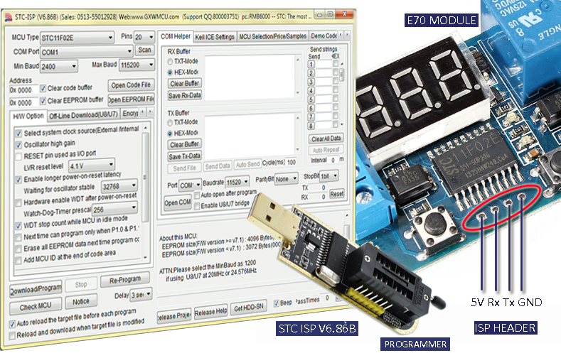
STC microcontrollers have a UART-/USB-based boot strap loader (BSL) that is also used to configure various device options using a proprietary protocol. While this protocol is not clearly documented, STC provides a good Windows GUI application (STC ISP) for programming these devices.
There is also an open-source STC MCU ISP flash tool available on GitHub. Named “stcgal,” the software provides a command-line flash programming tool for STC MCUs (8051-compatible microcontrollers). It is a full-featured replacement for STC’s Windows software and supports a wide range of MCUs. It is also very portable and suitable for automation.
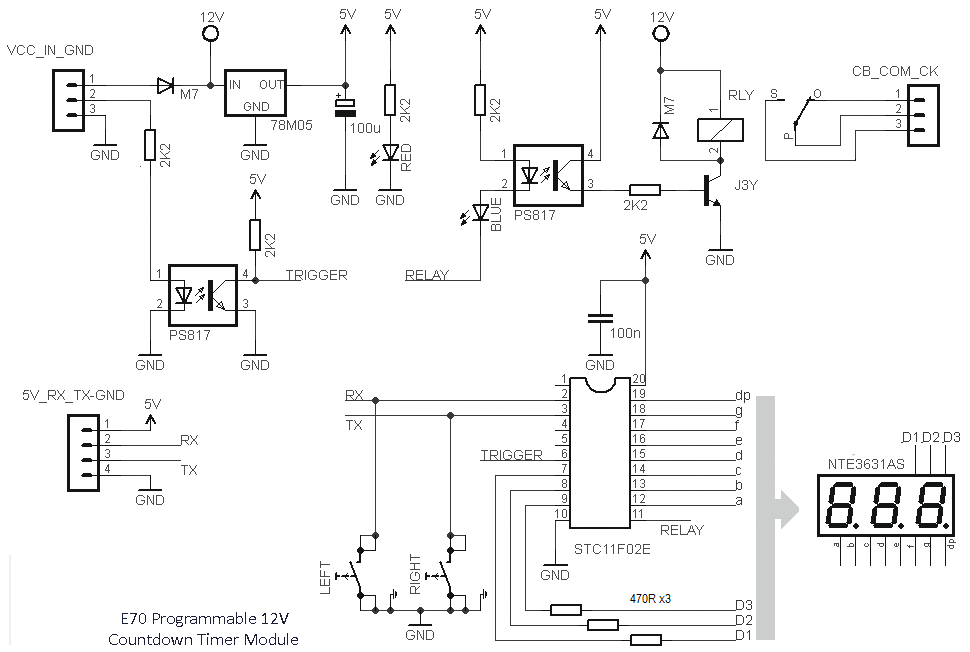
Ideally, I would have liked to get a hold of the schematic for the E70, but some quick digging around on AliExpress, Amazon, and eBay didn’t get me any results. So I picked up my reverse-engineering tools and prepared the schematic myself. Shown below is the double-tested schematic that I finally captured.

Preparation
In principle, there are two possible ways for hacking/reverse-engineering your E70 module. One is to just follow the original hardware setup, keeping it intact and preparing your own code to go with it. For example, you can write a code to convert the E70 from a countdown timer into a “000–999” universal event counter with a single logic-level trigger input, plus a relay to actuate a desired load when the event count reaches a threshold.
The other approach is to make whatever requisite changes you’ll need in the hardware and cook your code based on the new setup. For example, replace the display and/or the relay with headers to access their associated I/O ports (total 12 I/Os) for other intentions. You can also add a suitable crystal between pins 4 (XTL2) and 5 (XTL1) of the microcontroller for some innovative projects.
I should mention that, because “readout protection” is enabled on the microcontroller, the factory firmware cannot be extracted, and I have no source for it (not a biggie if you are not interested in the stock firmware itself but only in how the module can be changed). Additionally, I take no responsibility if you destroy your E70 while following my footsteps. You can easily replace the chip if you do, though.

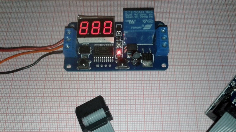
To jailbreak the E70, you will need an E70 module (of course), the STC ISP or the alternate stcgal, an STC programmer, and some wires/pogo pins. Nearly everything is commonly available from multiple vendors. Either you solder the wires onto the E70 or you can use pogo pins for flashing as you prefer.
Here is the exact procedure for performing the ISP using the STC programmer device and tool:
1. Select MCU type “STC11F02E” in STC ISP.
2. Load the new program code (*.hex or *.bin).
3. Select serial port (COM Port) of the connected programmer in STC ISP.
4. Configure the hardware option.
5. Press the “Download Program” button to download the program code.
What’s next?
Where to go from here? That’s up to you. As pointed out, the board as originally populated provides a three-digit display and a relay for controlling a power load. What might you do with that? If you remove them to access the I/O, you have even more options.

More importantly, though, the approach used here might lead you to look at options beyond this specific board. I acknowledge that the E70 is not the most useful of development boards, but the idea of jailbreaking an inexpensive commercial module that does have the hardware you need may be of interest for other projects. A lot is possible with the right idea, and the right software, when repurposing hardware.
Advertisement


