By Chintan Parikh, George Chen, and Nazzareno Rossetti, Maxim Integrated
Your car may be on its last legs, and you are in the market for a new one. Are you considering another gasoline-engine car, a full electric vehicle (EV), or something in between? With so many flavors of hybrid available, such as full-hybrid electric vehicles (FHEVs), plug-in–hybrid electric vehicles (PHEVs), or mild-hybrid electric vehicles (MHEVs), there are many options to choose from. Feels a bit like ordering your favorite flavor of latte, doesn’t it?
The trajectory of the automobile engine begins with the gasoline engine and ends with an electric motor. The force behind this dramatic transition is the necessity to meet ever-stricter fuel emission regulations. Currently, the gasoline engine uses the aid of an electric motor to help with both start-stop and regenerative braking applications, but its use will eventually fade. We project that automobiles will be fully electric 20 years from now.
A total ban of gasoline vehicles is expected around 2040. Strong candidates to accompany this transformation are the 48-V MHEVs, which help older gasoline engines meet emission standards at a modest cost (Fig. 1 ).
In this design solution, we will review the architecture of an MHEV and propose a buck converter that works with 48-V batteries while withstanding high-input-voltage load-dump transients and operating with low EMI, low duty cycles, and high efficiency.

Fig. 1: MEHVs are becoming a better option as gasoline fuel emissions standards get tougher to meet.
48-V auxiliary system
The MHEV belt starter generator (BSG) provides greater efficiency by replacing the alternator and starter motor of traditional cars with a single device that assists the powertrain (Fig. 2 ).
During braking, the energy flows from the combustion engine to the 48-V battery. The engine applies torque to the BSG, which, in response, acts as a generator. The electric waveforms generated by the BSG are rectified by the three-phase inverter via the IGBT or MOSFET intrinsic diodes, producing the DC current that charges the 48-V battery.
During start-stop, the energy flows from the 48-V battery to the BSG, which acts as a motor. In this phase, the BSG draws power from the 48-V battery through the three-phase inverter power transistors. A DC/DC converter bucks the 48 V down to 16 V to power the three-phase inverter gate drivers, providing the proper motion sequence to the BSG.
The BSG starts the engine during start-stop, provides torque boost to improve acceleration performance, and charges the battery during braking. The 48-V battery can also power accessories like fans, pumps, electric power steering racks, and compressors, as well as aid with start-stop systems. A 48-V battery can deliver the same power as a 12-V battery with one-fourth of the current, reducing the car electric wiring losses, size, and weight.
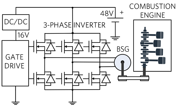 Fig. 2: A 48-V MHEV system
48-V battery
Let’s take, as an example, a 1-kWh, 48-V, 21-Ah lithium-ion MHEV battery. According to the “VDA 320 — Electric and Electronic Components in Motor Vehicles 48-V On-Board Power Supply” recommendation, the battery has an unlimited voltage operating range between 36 V and 52 V and allows limited operating modes between 20 V and 60 V and dynamic overvoltage up to 70 V. The maximum operating voltage (60 V) is the maximum permissible contact voltage safe for human operators so that the system is not classified as “high-voltage” with the risk of electrical shock.
48-V buck converter robustness
As discussed above, the 48-V buck converter can be subject to voltage spikes as high as 70 V and for as long as 40 ms, a very long time for electric stress. Operation at or above this limit can permanently damage the device. Accordingly, the buck converter input voltage’s absolute maximum rating must have enough margins above 70 V for safe operation.
Low EMI
The ECU’s power management electronics must withstand harsh automotive environments and be protected from electromagnetic interference (EMI). Accordingly, the 48-V buck converter must meet the CISPR25 Class 5 specifications for EMI. Fixed-frequency converters help with the spikes during both radiated and conducted emissions testing. Fixed and adjustable frequency allows design engineers to focus the filtering on a certain frequency to help pass EMI tests. By contrast, constant on-time architectures typically exhibit variable frequency, making it much more difficult to have good EMI performance.
Front-end 48-V buck converter
The automobile has dozens of electronic control units (ECUs). The typical ECU’s power management architecture is shown in Fig. 3 . The 48-V interfaces a robust front-end buck converter that withstands the battery’s static and dynamic voltage conditions and, in turn, helps power various gate drives for motor control with a 16–20 VOUT while also providing backup power to MCUs in case the 12-V battery gets disconnected.
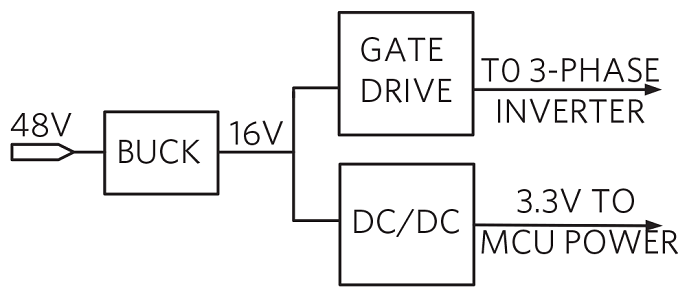 Fig. 3: ECU power distribution
Compared to 12-V input, the 48-V buck converter will tend to have higher switching losses
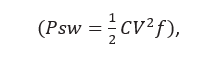
a problem that can be mitigated by reducing the frequency of operation (f) and adopting an advanced process with smaller minimum features and lower parasitic capacitances (C). In addition, the control technique must lend itself well to operation with low duty cycles. For example, a 16-V output and a 48-V input lead to

This means that the buck converter high-side transistor conducts only 33% of the time, while the low-side transistor conducts 67% of the time. Such considerations can guide the sizing of the power transistors for optimum performance.
Integrated solution
The MAX20059 is a high-efficiency, high-voltage, synchronous step-down DC/DC converter IC with integrated MOSFETs that operates over the 4.5-V to 72-V input voltage range. With an 80-V absolute maximum rating, the IC has a margin of 8-V versus 72-V operating condition and a 10-V versus 70-V battery dynamic overvoltage recommendation.
The IC is thoroughly tested according to VDA320 recommendations. As an example, Fig. 4 shows one of the tests, the transient overvoltage test, under conditions exceeding VDA320 recommendations:
- VIN = 14 V to 72 V
- VOUT = 12 V
- 0-A load 400 kHz, PWM
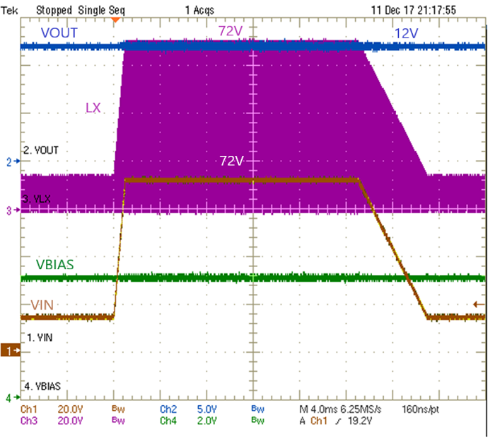
Fig. 4: Transient overvoltage test
The IC is also tested for electromagnetic radiation according to EMI CISPR25 Class 5 specifications. As an example, Fig. 5 shows one of many EMI tests, performed with a 200-MHz to 1-GHz log-periodic (horizontal) antenna. The IC level of emissions are well below the limit.
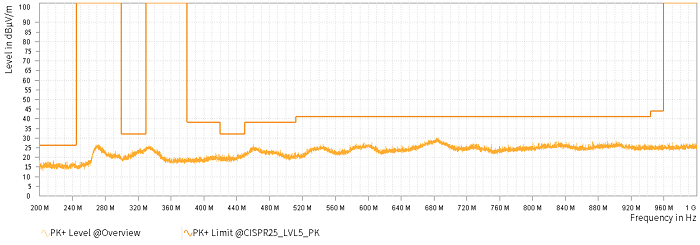
Fig. 5: Meeting the EMI CISPR25 Class 5 specification
The converter delivers up to 1-A current. Output voltage is programmable from 0.8 V to 90% VIN . The feedback voltage-regulation accuracy over –40°C to 125°C is ±1.5%. The IC features a peak current-mode control architecture and can be operated in the pulse-width modulation (PWM) or pulse-frequency modulation (PFM) control schemes. The IC is available in a 12-pin (3 × 3 mm) side-wettable TDFN package with an exposed pad for thermal heat dissipation. Fig. 6 shows the 48-V to 16-V typical application circuit.
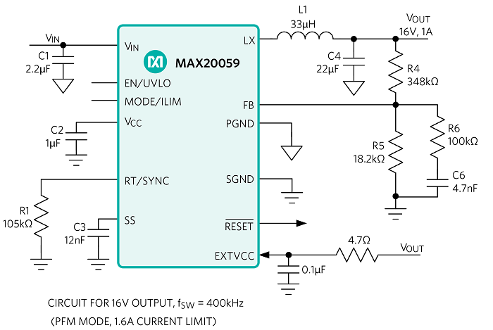
Fig 6: 48-VIN to 16-VOUT buck converter with 400-kHz switching frequency
High efficiency
For maximum flexibility, the IC has two modes of operation. PFM provides high efficiency across the operating range, but the output-voltage ripple is higher compared to PWM. PWM operation (Fig. 7 ) provides constant frequency operation at all loads and is useful in applications sensitive to switching frequency. Accordingly, the switching losses weigh higher at light loads, and the MAX20059 can achieve >90% peak efficiency from 48 VIN to 16 VOUT .
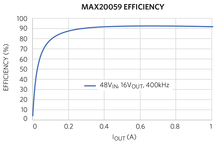
Fig. 7: 48-VIN to 16-VOUT buck converter efficiency at 400 kHz
Conclusion
The automotive environment is undergoing an epic transition. Due to the ever-increasing severity of fuel emission standards, the gasoline engine is on a descending parabola that will eventually end with a fully electric car. Meanwhile, hybrid implementations, such as the 48-V MHEV, are proliferating. We highlighted the challenges of designing voltage regulators that operate within the harsh 48-V automotive environment and presented a high-voltage front-end buck converter that has high tolerance to input voltage static and dynamic variations, low EMI, and high efficiency.
Glossary
- FHEV: A full hybrid electric vehicle has an auxiliary 200-V or 400-V battery of limited capacity.
- PHEV: A pluggable hybrid electric vehicle has an auxiliary 200-V or 400-V battery of higher capacity and is grid-rechargeable.
- MHEV: A mild hybrid electric vehicle has an auxiliary 48-V battery.
About the authors
Chintan Parikh is a director of business management at Maxim Integrated focusing on automotive power management solutions. Chintan holds a master’s degree in engineering management from Santa Clara University.
George Chen is a business manager at Maxim Integrated focusing on automotive power management solutions. George holds a master’s degree in electrical engineering from Arizona State University.
Nazzareno (Reno) Rossetti is an analog and power management expert at Maxim Integrated. He is a published author and holds several patents in this field. Reno holds a doctorate in electrical engineering from Politecnico di Torino, Italy.
Advertisement
Learn more about Electronic Products MagazineMaxim Integrated


