As demand for reliable signal isolation continues to grow in industrial, automotive, communications, and personal electronics applications, recent design trends have shifted from legacy isolation technologies such as optocouplers to digital isolators. Despite the prevalence of digital isolation, several common misconceptions persist regarding their effectiveness compared to optocouplers. Likewise, there are also several misconceptions or myths about the reliable performance and longevity of optocouplers. In this article, I’ll fact-check common myths about both devices.
What are optocouplers? What are digital isolators?
Before exploring these myths, let’s review the differences between these technologies:
- Optocouplers use a logic input to generate an input-side current. An LED transmits signals as light through a molding compound barrier to a receiving photodetector and an output located on the other side of the isolation barrier.
- Digital isolators use silicon-based complementary metal-oxide semiconductor (CMOS) technology with two integrated circuits (ICs) and a high-voltage dielectric built into the silicon process. Digital isolators translate digital signals into the high-frequency domain and send the signals through a capacitive-based high-voltage silicon dioxide dielectric barrier.
Optocoupler myth No. 1: Optocouplers have a reliable failure condition
There is a common misconception that optocouplers will always fail with an “open” circuit when a high-voltage event breaks the device. Although there are many ways that an optocoupler can fail open, it is also possible for an optocoupler to fail in “short” circuit, depending on the different failure modes in high-voltage systems.
Under the conditions of the first failure mode, when the voltage applied across the isolation barrier exceeds the rated limits for the isolator, the isolation barrier is capable of failing short, for both optocouplers and digital isolators. Texas Instruments (TI) has tested the first failure mode in its labs; the white paper “Understanding Failure Modes in Isolators” describes the observation of fail short results.
The second failure mode, where high voltage and high current damage circuits within the isolator, can lead to a fail-open situation for both device types. These high-voltage events can break enough of the device circuitry where they no longer function properly, but leave enough of the isolation barrier intact to still provide isolation.
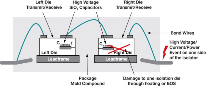
Figure 1a shows a high-voltage event on an optocoupler and Figure 1b shows a similar event on a digital isolator. Depending on the type of high-voltage event and the strength of the barrier, various levels of degradation can occur. To prevent a short failure caused by the first failure mode, you must select an isolator that meets or exceeds the electrical safety standards of your design.

(a)
(b)
Figure 1: Cross-sections of high-voltage events on one side of (a) an optocoupler and on (b) a digital isolator. (Source: Texas Instruments Inc.)
Optocoupler myth No. 2: The lifetime of an optocoupler is predictable, with little variation
For all electronic designs, it is critical to ensure that ICs will last for the lifetime of the product. This is especially true for isolation devices, given their role in protecting signals in the presence of multiple voltage domains. Although you may expect that two identical optocouplers would have very similar high-voltage lifetimes, there can actually be significant variation in high-voltage performance from device to device, usually because an optocoupler’s isolation barrier is created during the assembly phase of production.
Digital isolator manufacturers often build their isolation barrier in a more tightly controlled silicon wafer fabrication process. Figure 2 illustrates the differences in high-voltage lifetime and variation, where the high-voltage lifetime is higher and the distribution is much tighter for the TI digital isolators used in this testing. To learn more about this topic, see the white paper, “Improve Your System Performance by Replacing Optocouplers with Digital Isolators.”

Figure 2: Time-dependent dielectric breakdown of optocouplers and digital isolators. Click for a larger image.(Source: Texas Instruments Inc.)
Optocoupler myth No. 3: Optocoupler data-sheet specifications will last the lifetime of the device
You may not be aware that the light output of the LEDs in optocouplers degrades overtime, which has a direct effect on parameters such as the current transfer ratio (CTR). The mold compound inside an optocoupler turns yellow over time, resulting in less light transmitting through the isolation barrier, further degrading the CTR. Eventually the CTR will drop to a level where the device no longer operates normally, leading to high failure-in-time rates and a low mean time between failures.
To offset this, designers usually overdesign to account for the expected degradation over time, which can lead to higher initial power consumption. These issues are not always mentioned in optocoupler data sheets, making it difficult to account for in isolated designs. TI digital isolators, as an example, use a highly controlled fabrication manufacturing process and our data sheets do consider aging in the minimum or maximum specifications, helping set performance expectations throughout a device’s lifetime.
Optocoupler myth No. 4: Isolation is limited by an optocoupler’s maximum operating temperatures
Typical optocouplers are rated to an 85°C maximum operating temperature. Although there are optocouplers with higher temperature ratings available on the market, there are limited options and they are typically more expensive. Comparatively, digital isolators can easily support operating temperatures up to 125°C. For automotive designs that require temperature support up to 150°C, digital isolators like TI’s Grade 0-qualified ISO7741E-Q1 can help provide reliable system operation at peak ambient temperatures. Lower temperature ratings can be problematic for high-temperature designs where every component needs to reliably operate above 110°C. Otherwise, system performance or device lifetime could degrade at high temperatures.
Optocoupler myth No. 5: No primary-side supply means low power consumption
When configuring your system to reduce power consumption, it is important to consider how the inputs of an isolator are driven. Optocouplers are driven by a current input, while digital isolators are driven by a voltage input – either CMOS or transistor-transistor logic.
Optocouplers can drive digital device inputs such as microcontrollers, analog-to-digital converters, and digital-to-analog converters through a series resistor that controls the voltage and current. The input current will need to be as high as 10 mA to activate the LED and meet reliability over the product’s lifetime, which can lead to high power consumption at the input.
Digital isolators such as TI’s ISO7041 generally require <10 µA of standby current at a channel’s input. Figure 3 shows the current consumption vs. the data rate for the ISO7041. In this test, all four channels of the device consume less than 20 µA.
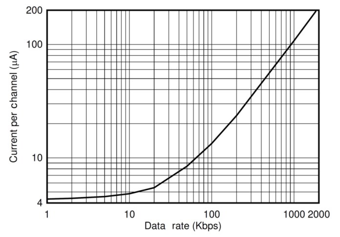
Figure 3: Current consumption vs. data rate for the ISO7041. Click for a larger image. (Source: Texas Instruments Inc.)
Digital isolator myth No. 1: Small digital isolator DTI indicates weak isolation performance
The distance through the insulation (DTI) of an isolator is the distance or thickness of the dielectric used for insulation between the high- and low-voltage sides. For optocouplers, the DTI is the distance between the LED and the photodetector. For capacitive-based digital isolators, the DTI is the distance between two plates of the capacitor.
With historical safety standards setting minimum DTI requirements based on optocoupler technology, there is a misconception that all isolators must have a DTI >0.4 mm to meet today’s stringent reinforced isolation certification requirements. In reality, however, the strength of an isolator’s barrier is a combination of the DTI as well as the high-voltage strength of the dielectric material.
Optocouplers have much lower dielectric strength, and therefore require a larger DTI. Capacitive-based digital isolators use silicon dioxide with a significantly higher dielectric strength and can support reinforced isolation with a DTI as low as 21 µm.
Organizations that manage safety standards for device operation have taken this into account over time and updated the regulations to allow thinner dielectrics based on the technology being evaluated. Table 1 lists the dielectric strength of different insulating materials.
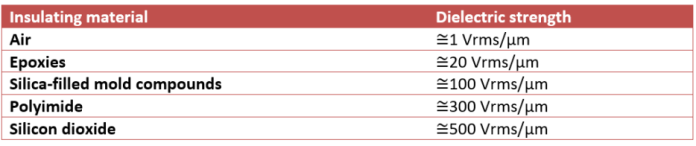
Table 1: Dielectric strength of common insulating materials. Click for a larger image. (Source: Texas Instruments Inc.)
Digital isolator myth No. 2: Digital isolators cost significantly more than optocouplers
Although this myth has historical relevance, digital isolator technology has advanced dramatically over the past decade to enable higher performance at lower cost. The ability to achieve high channel-count density in the same package is also beneficial to overall system cost. For example, the ISO6741 provides four channels of reinforced isolation in the same package, providing a strong isolation solution at a reasonable cost per channel.
Digital isolator myth No. 3: Digital isolator integration and saving board space comes at a cost
One of the greatest advantages of digital isolators is their ability to integrate other system requirements into the same package. Isolating interfaces such as controller area network, RS-485, I2C, and low-voltage differential signaling are great examples. You may worry that buying a digital isolator with an integrated transceiver will adversely affect your budget, but the truth is that there is a lot to gain with an integrated digital isolator, especially when compared to a similar discrete optocoupler solution.
The largest downside to a discrete optocoupler solution is the cost of the many discrete components (resistors, capacitors, diodes, Schmitt buffers, transistors) and the board space that they ultimately consume. Figure 4 compares the size of an optocoupler and the ISO1500 integrated RS-485 digital isolator. For more information about this comparison, see the technical article, “The Hidden Cost of Your Optocoupler for Isolated RS-485 Designs.”
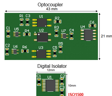
Figure 4: Printed circuit board comparison between discrete and fully integrated isolated RS-485 solutions (Source: Texas Instruments Inc.)
Conclusion
Digital isolation has come a long way over the past few decades and is now the go-to isolation solution for many designers. Keep in mind the myths and facts described in this article the next time your design calls for a reliable signal-isolation solution.
Advertisement
Learn more about Texas Instruments


