System-level design tools shine at DAC 1997
This year's Design Automation Conference (DAC)/ in Anaheim will showcase
several board and system-level design tools that automate new areas of
the design flow. Designers can glimpse the productivity and performance
benefits that are possible when synthesis techniques are applied at the
board-level for digital and mixed-signal designs. The continued integration
of system design will also be evident in demonstrations of software packages
that link multiple design functions for a specific application, such as
communications design.
IC designers can view a variety of tools intended to optimize chip performance
and improve designer productivity. EDA vendors are offering new ways to
evaluate design alternatives and to manage the efforts of designers working
on different platforms at different locations. For verification, several
companies will present formal verification tools and emulation products
offering the speed and computing power required in complex chip design.
System-level design
Omniview Galaxy from Omniview (San Mateo, CA) offers a
complete design environment for board- and system-level synthesis of digital
designs. The tool integrates a synthesis engine, a suite of component libraries,
development tools for user-defined custom libraries, and an interface to
popular EDA environments.
Beginning with a high-level description such as a block diagram, designers
can use the software to automate component selection, timing analysis,
and schematic generation. Users specify design parameters like cost, size,
and process technology, and the tool generates a list of possible designs.
For mixed-signal applications, two vendors provide Spice-based test-synthesis
products. Test Designer from Intusoft (San Pedro, CA) automates
test simulation, fault analysis and isolation, and generates detailed test-strategy
reports. The tool allows users to pair circuit configurations with various
analyses to create tests for component failure or out-of-tolerance conditions.
A series of tests can be run automatically with results summarized in a
test-strategy report.
From Opmaxx (Beaverton, OR), test synthesis is provided by a
family of design-analysis and automated-test tools. DesignMaxx performs
design centering of analog circuits by measuring design sensitivity during
circuit simulation.
FaultMaxx combines the results of sensitivity analysis with design-layout
and schematic data to perform fault modeling and computation for hard (catastrophic)
and soft (parametric) faults. TestMaxx generates a structured set of tests
for dc, ac, and transient conditions.
Some mixed-signal toolsets integrate the design flow for specific applications.
The HP Advanced Design System from Hewlett-Packard HP EEsof Division (Westlake Village, CA) merges all of the company's EDA technologies–system,
circuit, electromagnetic simulation, synthesis, and physical-design tools–to
cover the entire signal path in a single design environment.
A key feature is the integration and co-simulation of RF and DSP analysis
engines. In addition, the software is fully functional on both Unix and
PC platforms.
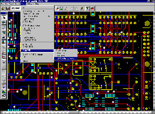
Two products address the need for electromechanical design. ViewCable
from Viewlogic Systems (Marlboro, MA) is integrated design and verification
software for electro-mechanical systems with interconnecting cables and
wire harnesses. The tool features a common database for the electrical
and physical attributes of component packaging and cabling. In addition,
the software supports simulation for signal-integrity and EMI/ EMC analysis
(see Fig. 1 ).

Fig. 1. ViewCable from Viewlogic Systems is integrated design and
verification software for electro-mechanical systems with interconnecting cables
and wire harnesses.
Analogy (Beaverton, OR) offers a Windows version of the company's
mixed-signal and mixed-technology simulator. SaberDesigner for NT promises
the same performance, functionality, and “look and feel” as the
existing Unix tool.
A variety of pc-board design tools will also be shown for the first
time. From Protel (Santa Clara, CA), Advanced PCB 3 is a Windows-based
pc-board layout system that enables the type of rules-based design offered
by Unix tools. The software allows electrical constraints to be automatically
incorporated into the physical design, which eliminates manual checking
between circuit design and board layout.
Power Links from OrCAD (Beaverton, OR) allows concurrent editing
of schematics and layout files by visually indicating the status of data
at each stage of the design. Users can transfer data bidirectionally between
OrCAD and Mentor Graphics programs and merge input from different design
sources into a single pc board.
PADS (Marlboro, MA) offers PowerPCB 2.0, a program that enables
the user to easily create design variations from a single pc-board design,
using a table-driven user interface. As variations are created, designers
can view their changes through a graphical preview option. Other features
include built-in design-for-test capabilities and split-plane definition
(see Fig. 2 ).

Fig. 2. PowerPCB 2.0 from PADS lets the user create design variations
from a single pc-board design, using a table-driven interface.
Pacific Numerix's (Scottsdale, AZ) PCB/MCM Signal Integrity analysis
program detects and corrects signal-integrity problems common to high-density
high-speed pc boards and multichip modules. The tool addresses wave propagation
delay, crosstalk noise, reflections, over and undershoot, and power and
ground bounce. Signal-integrity analysis can be performed before and after
physical design.
IC design
One of the challenges of complex chip design is to coordinate the efforts
of designers working in different locations. Synchronicity (Boston,
MA) is offering a family of design-management groupware to enable collaborative
design on the World Wide Web. DesignSync HLD, the first product in the
family, facilitates secure Web-based design through revision, release,
and configuration management.
Other products offer greater productivity by incorporating unique automation
features or support for multiple operating systems. For PLD design, Xilinx (San Jose, CA) introduces XACTstep version M1, a modular set of software
that improves productivity with pushbutton design flows and auto-interactive
tools. The tool also features improved place-and-route algorithms and support
for designs using EDIF, SDF, VHDL, and Verilog.
Cadence Design Systems (San Jose, CA) demonstrates the Windows
NT version of the Verilog-XL and Verilog-XL Turbo simulators, allowing
for mixed Unix and Windows design flows. The first release of Verilog-XL
includes the SimWave waveform editor.
Many of the tools on display pursue design optimization. An example
is Escalade's (Santa Clara, CA) Design Explorer, software that helps
designers optimize speed and area by automating design-space exploration.
An option to DesignBook, the language-independent tool includes features
such as design configuration, HDL generation, and results extraction and
visualization.
From Mentor Graphics (Wilson- ville, OR), Monet is an interactive
architectural exploration system for ASIC designers using behavioral-level
HDLs. The software allows designers to analyze architectural trade-offs
prior to RTL synthesis.
Sente (Chelmsford, MA) offers Release 2.3 of Wattwatcher power-analysis
software. The latest version supports VHDL simulators including Cadence's
Leapfrog, Model Technology's V/System, Synopsys' VSS, and Vantage's SpeedWave.
Formal verification tools are promising to lighten the task of verification
by applying formal methods to the early stages of the design process. Chrysalis
Symbolic Design (North Billerica, MA) offers Multi-Cycle Analyzer,
the second module in the Design Insight family of formal-verification tools.
The tool is a symbolic simulator that allows IC and ASIC designers to validate
complex sequential data paths, such as pipelined ALUs.
FormalCheck from Bell Labs Design Automation (Murray Hill, NJ)
uses a formal-verification methodology to functionally verify system-on-chip
designs, large functional blocks, and intellectual property. Users input
a design model in synthesizable VHDL or Verilog and then enter queries
to verify the design. Query templates eliminate the need to learn a formal-verification
language.
Emulation tools are also promising to play a greater role in verification.
Arkos, from Synopsys (Mountain View, CA), is an emulator and simulation
accelerator that offers extensive debug capability. The tool emulates designs
with up to 4 million gates and features fast compilation (250,000 gates
per hour) and run speeds. The emulator is tightly coupled to Cyclone, an
RTL cycle-based simulator that handles large designs, testbenches, and
memories.

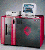
Fig. 3. CoBALT from Quickturn Design Systems is a
custom-processor-based logic emulator that compiles 1,000,000 logic
gates per hour.
CoBALT from Quickturn Design Systems (Mountain View, CA) is a
custom processor-based compiled code-emulator for ICs and systems (see
Fig. 3 ). The tool achieves very fast compile times–1 million gates
per hour–for designs with up to 8 million gates.
–David Morrison and Spencer Chin
Advertisement


