Selecting single-phase
rectifiers for telecom
power supply systems
Cooling and electrical needs are among the key
considerations in choosing a rectifier
BY ALAN GOBBI
Advance Power
Solon, OH
The designer must carefully consider several requirements when selecting a single-phase power rectifier module for a telecom application. These include cooling, input voltage, current limiting, operating temperature, the way the rectifier is connected to the rest of the power system, and the signal features of the telecom system.

Selecting a rectifier for a telecom power system requires attention to cooling,
operating temperature, electrical parameters, and system connectivity.
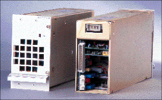
Shown here is Advance Power's TWF 0400 rectifier.
Cooling methods
The cooling method employed in the telecommunications power system is perhaps the most critical consideration in choosing a rectifier. In fact, the choice of cooling regime can affect the rectifier's physical size by a factor of up to 2.5.
Fan cooling and convection cooling are the main methods used to cool a rectifier. Telecom systems have traditionally favored convection cooling for its low maintenance cost and long product life compared to that of fans, which add cost and impose noise and space penalties.
However, a poorly designed enclosure using convection-cooled rectifiers can result in a system that is much more unreliable than a system using fan-cooled rectifiers. Hot spots in convection-cooled systems can be difficult to avoid. A convection-cooled rectifier requires an efficient enclosure design to achieve optimal cooling. Critical semiconductors in fan-cooled products can be more reliable because they exhibit lower temperature rises than in comparable convection-cooled systems.
New rectifiers have alarm and control features that can monitor fan performance and allow the rectifiers to be easily replaced in the field. Thus, fan-cooled rectifiers can be reliably maintained in a cost-effective manner.
In addition to fan and convection cooling, external system cooling and assisted convection can also be used. In external system cooling, the rectifier's convection cooling is supplemented by forced air flow provided by the system enclosure. This approach enables higher power densities to be achieved without some of the space and noise constraints imposed by fans in the rectifier. Forced air flow is particularly useful in applications where the power system is integrated into the full tele-communications system.
Assisted convection cooling can be used when rectifier conditions require part-time fans to supplement the rectifier's convection cooling. This is particularly common if temperatures are high or if high output currents are sustained. High system integrity can be maintained by running the fans and routinely monitoring their performance.
Input voltage
Another critical factor in rectifier selection is the input voltage range. Designers now often specify input ranges to suit world voltage ranges of 85 to 264 V or more. In practice, for most applications, neither end of the voltage range is optimum. Providing full parametric performance over a wide input voltage range can significantly increase the rectifier's cost and size, as well as increase the amount of cooling required.
Some applications require rectifiers to operate fully over wide input voltage ranges. However, other applications require only short-term capability for input voltages below a threshold level. Thus, careful selection of input voltage range can eliminate the need to manage the power dissipation on a continuous basis, resulting in substantial cost and size savings.
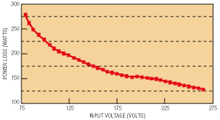
If a system is required to operate from a nominal 115-V supply, the percentage difference in maximum power loss in the rectifiers between operating at 103.5 V (115 V – 10%) and 85 V can be up to 15%. Systems specified to operate continuously from 85 V need to reliably dissipate about 15% more power than a system specified for 103.5-V continuous operation.
A continuous thermal rating of 103.5 V does not imply that the system can not reliably support short-term operation at substantially lower voltages. The precise limitations depend upon the thermal management within the rectifier. Figure 1 shows the power loss for a typical rectifier.

Fig. 1. In a universal-input rectifier, power loss decreases as
input voltage increases.
Current limiting
When selecting a power rectifier, the designer should also be aware of the power system's current-limiting characteristics. Traditionally, the power system exhibits a constant-current-limit characteristic over its output voltage range with either a foldback characteristic or constant-current limit down to a short circuit.
However, this approach may not be ideal in a telecom power system, where the total load is the sum of many smaller loads. Here, load elements are either resistive, constant-current, or constant. Power and battery elements take varying currents, depending on their charge status. If the maximum total load current–including battery-charge current allowance–is used to size a power system at the maximum battery float voltage, more power capacity than needed may be provided.
Modern telecommunications systems tend to use local dc/dc converters providing fixed-output voltages independent of the power system bus voltage. This constant-power demand results in an increasing input current as the bus voltage falls. A constant-power load that consumes 1 A at 55 V consumes 1.3 A at 40 V.
By contrast, a constant-resistance load of 1 A at 55 V will consume only 0.7 A at 40 V. Carefully assessing the nature of all loads across the full operating voltage range dictates if it is possible to optimize a system by providing an output current-limit characteristic other than traditional constant current.
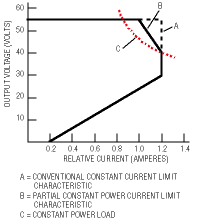
When selecting a rectifier, the designer should be aware that the output characteristic of a modern switched-mode rectifier can be easily tailored to suit total load requirements, minimizing the total installed power requirements for a particular load combination.Figure 2 shows the output load characteristic for a rectifier optimized to suit a load with a mainly dc/dc configuration. The triangular area between A and B represents a 17% reduction in power requirements.

Fig. 2. A rectifier's output current limit characteristic can be
optimized to suit total load needs, shown here in the triangular area between
A and B representing a 17% reduction in power requirements.
Temperature range
Another key consideration when selecting a rectifier is the operating temperature range of the telecom equipment. To minimize cost and maximize a power system's capability, the designer must look closely at the temperature extremes and determine if full performance is required.
More specifically, some equipment may require continuous low-temperature operation without any performance compromises, in which case the power system must be fully rated and meet all parameters. But in other applications where low-temperature operation is required only briefly, the user can save costs by specifying the rectifier to start up at the lowest required temperature and fully meet all parametric requirements at a higher temperature.
At the high-temperature end, normal power supplies required to operate at high ambient temperatures are sometimes derated above a certain temperature. This can equate to as much as a 30% reduction in power for a 20°C ambient temperature increase.
With rectifiers, the output is required to operate in voltage control when batteries are in a high charge state. But when batteries are recovering from a discharge, rectifiers must operate for a sustained time period in a current-limit mode. If a rectifier must operate at a derated temperature in current limit, its current limit must be reduced to ensure that the rectifier's power capability–in the worst-case ambient temperature–is not exceeded. In effect, the higher the ambient temperature, the lower the continuous rectifier current needs to be.
Signal requirements
With the right thermal management and monitoring features within a rectifier it is possible to automatically offer more power at lower temperatures. Otherwise, the rectifier's output capability would be restricted to the safe power level that can be sustained at the maximum ambient temperature.
Thus, alarm signals and other control features should be factored into the rectifier selection. Sometimes only an output-healthy/rectifier-fail alarm signal is needed, but other times the rectifier must incorporate a very sophisticated signal package, with or without local displays.
Rectifiers with intelligent signal packages give the end user easily programmable options such as output current signal, current-limit programming, forced-current share, and battery temperature compensation. A low-voltage-disconnect module inside a rectifier is another enhancement for some medium-power applications. This module prevents permanent battery damage when the power mains fail and the battery voltage falls below a threshold level.
Connectivity
Another issue to consider is the way that a rectifier is connected to a system. The three ports that need to be connected are the ac input, dc output, and alarm signals. Basic rectifiers can have a screw terminal for the power connections and a simple multipin signal connector, but these are becoming unpopular because they are relatively difficult to install or replace.
A popular alternative is a hot-plug rectifier. This unit can be automatically connected to the ac supply, the dc bus, and alarms monitoring circuits as the product is slid on to its support shelf. Installation or removal requires no real skill.
Hot-plug rectifiers cost more to produce than more basic products with screw terminal connections. However, if the cost of installation and maintenance is taken into account, they can be more cost effective than basic rectifiers.
Other rectifiers that fall in between the basic and the hot-plug types are also available. A unit with an input connector, output connector, and signal connector that does not automatically make connections as it is installed on a shelf can still be hot swapped. However, this process requires greater skill to ensure that the system integrity is maintained during the process of changing or installing a rectifier.
The right choice of connectivity for a rectifier depends greatly on the application and location. Hot-plug rectifiers are preferable in a remote location and where installation or maintenance has to be done without a skilled worker. Where skilled technicians are available, a more basic rectifier may be more suitable.
Advertisement


