A/D and D/A converters
trade off performance and
resolution
Different architectures suit a wide range
of signal-processing applications
BY KUSH PARIKH
Texas Instruments
Dallas, Texas
Because they interface to the real world, analog-to-digital (A/D) converters and digital-to-analog (D/A) converters are vital in today's digital-signal-processing systems such as multimedia PCs and wireless communication systems. The performance of these converters is determined in large part by their architecture–the way in which a particular device is structured and operates. This performance can be measured in a number of ways.
Two of the more prominent performance criteria are speed (the number of times the input signal is sampled in a finite amount of time) and resolution or precision (expressed as a number of bits of accuracy). In many cases, there is a tradeoff between speed and resolution. Depending on the application, system designers will implement a certain data converter architecture to optimize one of these parameters.
Four distinct A/D converter architectures are in use today: flash, pipeline, successive-approximation register, and sigma delta. For D/A converters, there are two main architectures–resistor and current mode –which are then divided into subcategories. Resistor D/A converters include resistor-string and R-2R converters, while current-mode D/A converters consist of current-steering single-ended, current-mode-differential, and continuously calibrating converters (see Fig. 1 ).

Fig. 1. The various A/D and D/A converter architectures allow designers to
trade off design criteria such as speed, resolution, power, and cost.
A/D converters
Flash. The fastest of the A/D converter architectures, flash converters were first used in video applications because of their speed, even though they have limited resolution. Flash A/D converters achieve sampling rates as high as 300 Msamples/s.
Flash devices such as Texas Instruments' TLC5501 perform multiple word-at-a-time conversions in parallel (see Fig. 2 ). The input signal is connected to a bank of fast comparators. For a flash converter to reach an effective resolution of n bits, the flash architecture must incorporate 2n – 1 comparators. This requires a large silicon die for the converter chip, which in turn drives up the cost and power consumption of the device.
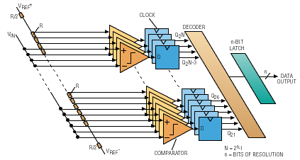
Fig. 2. With sampling rates as high as 300 Msamples/s, flash converters
are the fastest of the A/D converters, but they are limited to resolutions of 8
bits and below.
Input capacitance is also very high because of the 2n – 1 comparators in parallel. Because of its high cost and power requirements, the flash architecture is usually only used when a pipeline or semiflash A/D converter will not meet the speed requirements of the system. Flash A/D converters are also limited to resolutions of 8 bits and below.
Semiflash and pipeline. To achieve higher resolutions in the range of 10 to 12 bits, a multistep flash or semiflash architecture was developed. This architecture, which was used in Texas Instruments' TLC5510 8-bit 20-Msample/s A/D converter, divides the input signal range into a number of subranges through the use of banks of comparators, much like the flash architecture. However, the multistep arrangement has a smaller die size, lower cost, and reduced power consumption over flash because the multistep architecture requires fewer comparators.
The pipeline A/D converter architecture is so named because of the arrangement of the different stages of the conversion process (see Fig. 3 ). Pipeline A/D converters, are used extensively for medium-to-high-speed conversions in the range of 1 to 80 Msamples/s with medium resolutions of 8 to 12 bits.
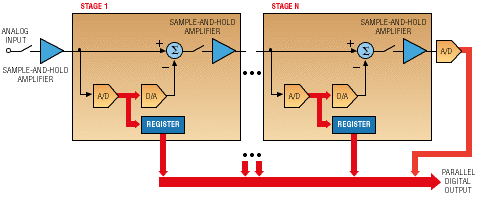
Fig. 3. Pipeline A/D converters typically perform medium-to-high-speed
conversions in the range of 1 to 80 Msamples/s with resolutions of 8 to 12 bits.
In a pipeline architecture, each stage is preceded by a sample-and-hold amplifier that samples the input signal and holds it constant while the conversion is performed. Each converter section has a resolution of 1 to 4 bits. The output of each converter section is then reconverted back into analog form by a D/A converter, and this is subtracted from the held-input-signal level. The resulting voltage, or residue, is then sampled and held by the amplifier of the next stage and the process is repeated through completion.
After the pipeline is filled, a value is output on each clock pulse. The number of clock cycles needed to fill the pipeline is referred to as latency. Hence, valid data are read after the pipeline fills and before the pipeline empties. In addition, chip area is significantly reduced and the input capacitance–when compared to that of the flash architecture–is lower by an order of magnitude.
Successive-approximation register. A/D converters based on the successive-approximation-register (SAR) architecture achieve a higher resolution in the 8 to 14-bit range, but the sampling rate of up to 1 Msample/s is slower than the flash or pipeline architectures. Successive-approximation converters are used extensively in many different applications because the base architecture can deliver a wide range of speeds and resolutions.
The key to the SAR architecture is that it is based on just one comparator (see Fig. 4 ). To achieve n bits of resolution, a successive-approximation converter must perform n comparator operations, each of which is stored sequentially in the architecture's register. Therefore, a successive-approximation A/D converter with 12 bits of resolution would execute 12 comparisons on each input signal.
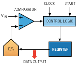
Fig. 4. Successive-approximation-register A/D converters,
which provide 8 to 14 bits of resolution, are popular because
of their low power consumption, but their speeds are limited to
1 Msample/s.
The fact that this architecture is based on a single comparator leads to a very small die size and, therefore, low power consumption. This has made SAR converters very popular in recent years.
However, regardless of the IC fabrication process, SAR sample rates are inversely proportional to resolution because the conversion method requires one clock cycle to produce each bit of resolution in the output data. With today's technology, the maximum practical sample rate for an SAR A/D converter is effectively limited to approximately 1 Msample/s.
Sigma delta. The sigma-delta architecture is capable of very high resolutions in the range of 16 to 24 bits. This high resolution restricts the architecture's sampling speed to approximately 48 ksamples/s.
Sigma-delta converters, such as Texas Instruments' 20-bit 40-ksample/s TLC320AD75, use a technique called oversampling, which is based on the theory that a very fast, low-resolution converter can take a large number of samples on an analog signal. The outputs from this oversampling process are then combined into groups, and the groups are averaged using a digital filter like an accumulator-adder (see Fig. 5 ).
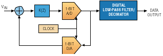
Fig. 5. Offering resolutions of 16 to 24 bits, sigma-delta A/D converters
are the most precise of the various architectures, but at the expense
of slower operation with sampling rates up to just 48 ksamples/s.
This averaging operation can increase the accuracy of the conversion as long as the input signal does not vary any faster than the sampling rate. This process also eliminates any in-band noise present in the A/D converter by spreading the noise across the entire sampling-frequency band.
Sigma-delta converters use a fairly simple analog anti-aliasing filter, resulting in a very cost-effective A/D converter. This is achieved because decimation and low-pass filtering is done digitally so that the anti-aliasing filter becomes a simple single-pole RC filter.
D/A converters: Resistor architectures
Resistor string. The resistor-string architecture uses a series of resistors to decode digital data and convert the data to an analog signal. The decoder effectively acts as a 2n multiplexer (where n is the number of bits of resolution) that selects the proper voltage output.
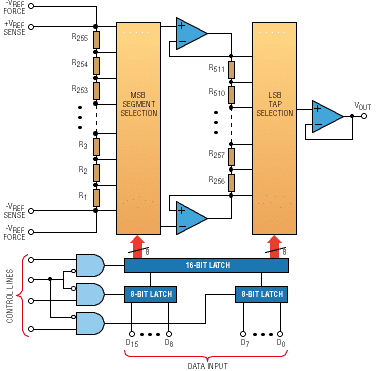
Fig. 6. D/A converters that use the resistor-string architecture
feature low current consumption, sampling speeds up to 1 Msample/s, 8 to
12-bit resolution,and a differential-nonlinearity error of less than 1 LSB.
The typical impedance of a resistor-string converter is limited to around 100 kilohm. This results in a low current consumption of approximately 50 µA, while still allowing sampling speeds in the range of 1 Msample/s. Some resistor-string converters provide increased drive capability by using an output amplifier to buffer the resistor string with respect to the external load.
In addition to low power consumption, the process of resistor matching results in a very good differential-nonlinearity characteristic that is less than 1 LSB. This is a critical requirement for a system that might require no missing codes.
The main disadvantage of the resistor-string architecture is that increasing resolution requires an increasing number of resistors. Typical resistor-string converters are limited to resolutions of 8 to 12 bits. Higher resolutions are possible by segmenting the input digital data for processing by distinct resistor strings. The output of these segmented resistor strings are then summed, allowing resolutions up to 14 bits.
R-2R. These converters use a network of resistors arranged spatially as a ladder with the horizontal segments of the ladder equal to R number of resistors and the vertical segments of the ladder, which are connected to ground, equal to 2R number of resistors. The resistor network is followed by an op amp that converts the current output to a voltage output.
The R-2R architecture has the advantage of being more compact than a straight-line resistor-string arrangement and can achieve high resolution in the range of 8 to 14 bits. R-2R converters, like the 8-bit TLC7524 from Texas Instruments, can reach a fast settling time of approximately 100 ns because their output is a current. As a result, R-2R converters achieve high speeds, but an external op amp is needed to convert current to voltage, since voltages are required in most applications.
Higher cost is another consideration. Many R-2R converters require fabrication processes that involve implementing the resistors with expensive thin-film techniques. Additionally, each resistor must be trimmed individually with a laser, again driving up costs.
D/A converters: Current-mode architectures
Current-steering single ended (graphics). The fundamental structure of a current-steering D/A converter is an array of current sources that can be individually turned on or off by a digital signal. In the thermometer-code configuration, the array contains 2n -1 identical current sources, where n is the number of bits of resolution. Another type–the binary code–consists of n current sources, where the value of each source is binary weighted. The term current steering derives from the fact that the output is a fixed current that is steered either to the load or ground.
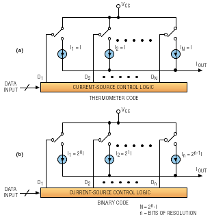
Fig. 7. Current-mode D/A converters achieve speeds of 10 to 300
Msamples/s by switching on and off an array of current sources arranged in
either a thermometer-code (a) or binary-code (b) configuration.
Current-steering D/A converters have inherently high speeds in the range of 10 to 300 Msamples/s, but resolution falls in the 8 to 12-bit range. Current-steering D/A converters are well suited to driving coaxial cables, which makes them popular in PCs and workstations for driving display monitors.
Current-steering D/A converters are compact in size and use power efficiently. Fifty percent of the total power consumption of the device often ends up in the load.
Current-mode differential (communications) . This type of converter operates on the same principles as a current-steering graphics D/A converter, but is optimized for communications applications such as digital modulators. Communications D/A converters are similar to graphics D/A converters in speed and resolution, but have better ac performance.
Instead of a single current output and a single termination resistor, communications D/A converters have two complementary outputs. Each current source is steered to one or the other of the outputs.
Since they are fully differential, communications D/A converters cancel some of the spurious harmonics that would be found in the output of other converters. This leads to improved performance on characteristics such as spurious-free dynamic range, total harmonic distortion, signal-to-noise ratio plus distortion, and intermodulation distortion.
Continuously calibrating. Another variation of the current-steering architecture is the continuously calibrating D/A converter. As the name suggests, each current source in this converter is individually calibrated. Typically, a round-robin calibration scheme is used whereby one current source is removed at a time and calibrated.
Continuously calibrating D/A converters are optimized for high resolutions of 14 bits or more, and the output of these devices is fully differential. When speed and power consumption are not major concerns, a fully differential-output amplifier often follows the continuously calibrating D/A converter to simplify the design of the converter itself and to improve performance. Although continuously calibrating D/A converters were first developed in the early 1980s for digital-audio applications, they are now being used extensively in high-speed high-resolution modulation.
Advertisement


