Selecting drivers/receivers
to maximize signal integrity
Topology, signaling rate, and transmission distance, as well as
power and interchangeability, must be specified
BY JIM DIETZ
Texas Instruments, Dallas, TX
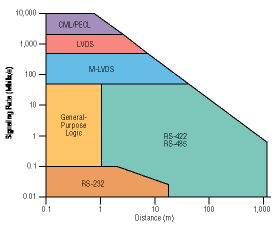
http://www.ti.comAt the heart of most electronic systems is a processor to manipulate digital inputs to produce a value-added output. Choosing among the various processing solutions is often the first system decision. Selecting correct drivers and receivers closely follows the processor selection. Device requirements When choosing a processor, designers are concerned with clock rate, memory, and MIPS. For drivers and receivers, they must specify topology, signaling rate, and transmission distance, as well as power and interchangeability. Topology Topology refers to the number of nodes to be interconnected. The most basic topology is point-to-point (simplex), encompassing one driver and one receiver. Simplex provides the highest signal quality since the path between driver and receiver is uncomplicated. Designers often implement clock distribution trees with simplex interfaces to maximize signal integrity. Simplex architectures are also a better choice when the speed of an interface gets above a few hundred megabits per second. RS-232 and LVDS (TIA/EIA-644) are simplex standards. Multidrop and multipoint are the next level of complexity in driver/receiver topology. Multidrop refers to a single driver communicating with multiple receivers. Having more than one receiver creates stubs from the main bus line. These stubs appear as discontinuities, which degrade signal quality. LVDS (TIA/EIA-644-A) was recently updated to support multi- drop operation. Multipoint architectures have more than one driver connected to one or more receivers. Multipoint is chosen when multiple nodes on a bus need to be active transmitters. An industrial-control application may have motors, sensors, and processors interconnected, so that speeds, positions, and temperatures can be shared for the processors to issue torque and position commands. RS-485 and M-LVDS are examples of multipoint industry standards. Signaling rate After specifying the topology, signaling rate must be specified. Clock signals are specified in megahertz. Data transmission is specified in megabits per second. Clock frequencies in megahertz can be converted to signaling rates in megabits per second by multiplying by 2. Transmission distance Transmission distance is another key parameter. Many drivers and receivers are specifically designed for short applications. These limitations come about due to the signaling employed (single ended vs. differential), the voltage levels used and the common-mode voltage range of the receivers. An inverse relationship exists between signaling rate and transmission distance. For many devices, the signaling rate will decrease with distance. This inverse relationship is due to intersymbol interference (ISI). Cables and etches filter sharp signal edges from a driver resulting in separate bit pulses that interfere at the far end of the line. This ISI is quantified as jitter. Jitter magnitude increases with distance. Assuming a constant metric for acceptable jitter (measured as a percentage of the bit period), it is easy to understand this inverse relationship. Power and interchangeability Additional parameters that need consideration include power and interchangeability. Also, the device's current draw under loaded conditions needs to be specified. When faced with alternative solutions, the lower power solution will generally be chosen. Interchangeability refers to standard compliance, as well as common footprints, or pinout. Standard compliance is generally preferred over proprietary solutions. Standard interfaces allow different subsystems to be designed by different entities, with the expectation that the integration will be smooth. Standard compliance and common footprints ensure availability of supply and competition among suppliers. Device selection The choice of available drivers and receivers can be daunting. Fortunately, practical solutions can be quickly narrowed down. Using topology first, the designer must understand that simplex, multidrop, and multipoint devices represent an ascending list of applicability. Multidrop devices can be used in simplex or multidrop applications. The opposite is not always true. Likewise, multipoint devices can be applied to simplex, multidrop, and multi-point problems. The maximum signaling rate must also be considered at this time. Attempts to implement a 1-Gbit/s multidrop system will likely fail. Multidrop and multipoint designs will generally be limited to a few hundred megabits per second. Signaling rate and distance are best treated together when choosing among alternative devices. As shown in Fig. 1 , signaling rate decreases as transmission distance is increased. Starting at the lower left corner, general-purpose single-ended logic (BTL, GTL, and GTLP) provide coverage below 1 m and up to 50 Mbits/s.

Fig. 1. As transmission distance increases, signaling rates decrease for all types of drivers and receivers.
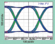
When the transmission distance is longer, more-robust drivers are needed. For data transmission up to 20 m and below 100 kbits/s, RS-232 devices can be employed. RS-232 devices are single-ended and employ large voltage swings, implying high power. When a design calls for transmission beyond 1 m, and above 100 kbits/s, differential signaling is needed. Attempting single-ended signaling above 100 kbits/s demands too high a driver slew rate. Differential signaling provides inherent noise immunity (due to receiver common-mode noise rejection), thereby allowing smaller voltage swings. RS-422 (multidrop) and RS-485 (multipoint) allow operation to 50 Mbits/s and reach distances greater than 1 km at lower rates. LVDS If higher rates are required, LVDS devices signal into multiple gigabits per second. LVDS uses a small differential signal. This small signal allows faster switching, but limits applicability to tens of meters. M-LVDS, a variant of LVDS, provides signaling to 500 Mbits/s and extends applicability of LVDS to multipoint and heavily loaded backplanes. PECL and CML As signaling rate increases beyond 2 Gbits/s, available solutions include PECL and CML devices. These devices continue to set the standard in high-speed signaling, but require higher load current. Before leaving Fig. 1 , a few points are noted. First, higher-speed/ longer-distance devices can be used for lower-speed/shorter-distance problems. An LVDS solution could be used for distribution of a 1-MHz clock 4 in. across a backplane, as could an RS-422 or an RS-485. The lower electromagnetic emissions of an LVDS solution often lead to its selection for such a problem. When considering signaling rate for devices, it's important to note that a maximum signaling rate may often be featured based on a minimally acceptable parametric quality, such as output voltage, transition time, or jitter. Standards often do not dictate how these parameters are related, but some rules of thumb can be employed. To ensure optimum operation, transition times should be limited to less than 50% of the bit time, while device jitter should be 10% to 20% of the bit time when tested with random data. These rules help ensure that adequate signal voltage and timing margin will be available at the system level, as seen in an eye diagram for a 2-Gbit/s LVDS repeater that complies with these suggestions ( see Fig. 2) . The input is 2 Gbits/s of random data. Output jitter is 55 ps (source jitter of 25 ps), while the transition time is 160 ps.

Fig. 2. To ensure optimum operation, transition times should be limited to less than 50% of the bit time, while device jitter should be 10% to 20% of the bit time when tested with random data.
The power a driver consumes relates to the signal voltage. RS-485 has a swing of ±2 V, while M-LVDS uses ±0.6 V. As an example, in a design requiring multipoint signaling at 10 Mbits/s and 10 m, both M-LVDS and RS-485 are feasible. For single-channel operation, good choices are Texas Instruments' SN65MLVD201 and SN65HVD20. Both devices offer the same footprint, are standard compliant, and can meet the specifications. In this case using the SN65HVD20 requires four times the power needed with the SN65MLVD201. The extra power in the SN65HVD20 is used to generate a higher-voltage signal. While this power may not be needed for this application, it becomes an enabler when the design problem extends to 100 m. In fact, the SN65HVD20 allows signaling at rates above 1 Mbit/s, while the transmission distance increases to 500 m.
Advertisement


