Meeting emerging power conversion efficiency needs
New ICs help overcome limitations of traditional topologies
BY SRI JANDHYALA and DENNIS SOLLEY
ON Semiconductor
Phoenix, AZ
http://www.onsemi.com
Energy consumption is a hot topic today, and energy conservation has taken on new importance. Many electronic devices have become an essential part of our daily lives, and reducing the energy consumption of these devices will have a significant impact. New IC technologies enable these energy savings while keeping all the needed features and performance at a low cost. Good progress has been made recently on reducing the standby power via activities such as the 1-Watt Initiative, and the focus is now shifting to active mode.
In the U.S., the efforts of the EPA EnergyStar program have resulted in the specification for minimum efficiencies at various load factors for computers, which is set to take effect on July 20, 2007. EnergyStar is working on or has similar guidelines for enterprise servers, external power supply modules, and cable set-top-boxes. The EnergyStar guidelines are quickly being adopted by Japan, China, Europe, and Australia. The power supply plays a key role in reducing the power consumption, and a renewed focus to improve the efficiencies has emerged. In this article, two topologies that provide a means to higher efficiency while keeping costs in check are described and compared to traditional methods.
Traditional topologies
Factors that drive the choice of topology include the input voltage range, output current, and output voltage(s), required efficiency targets at different loading conditions. Historically, the choice of topologies employed in commercial, high-volume power supplies have been driven by cost, familiarity of the topology for the designer, and the availability of components.
The more popular traditional topologies are the single-switch forward (1-Sw), two-switch forward (2-Sw), and two-switch half-bridge (HB) formats. These provide robust cost-effective solutions, but they may not be able to achieve required efficiencies cost effectively. The typical desktop or other high-volume power supply may achieve peak efficiencies in the high 60% or low 70% range and much worse at light loads. Efficiency of 80% is now neededand at 20%, 50%, and 100% of rated loads. The designs must also continue to keep the standby power consumption very low.
Switch forward
The switch-forward topology (see Fig. 1) has been extremely popular and very easy to design, being robust and low cost and having a low component count. At or near full load, the efficiency of this topology is constrained by its 50% duty cycle limit that keeps the turns ratio relatively low and the primary current relatively high. At lighter loads, switching losses contribute to poor efficiency. In many modern designs, a PFC front-end is employed to reduce harmonic currents. With PFC output voltage in the 400-V range, the single-switch forward approach is also forced to use a switch FET rated at >900 V, which adds cost.
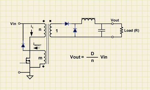
Fig. 1. The 1-Sw forward topology is simple and robust.
2-Sw switch forward
The 2-Sw switch-forward topology (see Fig. 2 ) is a modification of the 1-switch design to address the switch voltage constraint. It reduces the voltage rating on the switch to the maximum input voltage, but does require two switches, and is still a hard-switching topology that has high switching losses. The other added complexity is the need to drive the high-side MOSFET by using a boost circuit and driver.
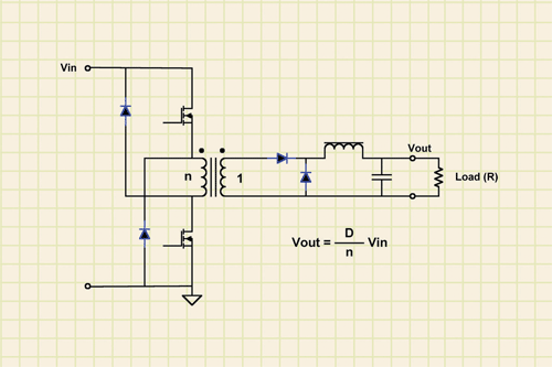
Fig. 2. The 2-Sw forward topology lowers the voltage requirement of the switch transistors.
Half-bridge
The half-bridge converter (see Fig. 3 ) is an alternative for higher power requirements. As opposed to the 1-Sw or 2-Sw forward converters, the HB converter allows two-quadrant operation and reduces the primary FET current stresses, and the FET voltage stress is similar to the 2-Sw forward converter. With transformer construction and output rectification more complex than the simple forward topologies, the half-bridge converter also suffers from high switching losses like the forward converters.
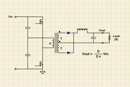
Fig. 3. The half-bridge topology fits higher current applications.
Emerging topologies
These topologies are not really new—they have been around for a long time—it is the application of these topologies in the commercial, higher volume applications that is new, because of higher efficiency requirements and new IC’s that make them cost effective.
Active-clamp forward
The active-clamp forward topology (see Fig. 4 ) is a soft-switching topology and though it is similar to the traditional forward topologies, it has been historically viewed as hard-to-implement and as a result, its use has been limited to very specific higher power applications, primarily in telecom.
In this design, the transformer is reset using a capacitor in series with an auxiliary switch, during the entire off time of the main switch. This eliminates the dead time of the single switch forward design. This topology has the ability to achieve very high efficiencies across the load spectrum due to low switching losses and operation above 50% duty cycle. Operating over extended duty cycles allows for a lower primary current, thereby reducing the stress on the switch. Further, this topology provides self-driven synchronous rectification. With the ever-lower cost of the low-voltage MOSFETs, their use in synchronous rectification has become a viable option for low-output-voltage high-current requirements. The use of the active-clamp components and the control for the active-clamp FET may appear to add complexity, but this is offset by the elimination of snubbers, reset circuitry, and the lower overall switch requirements. This topology also allows for operation over a wide input voltage range.
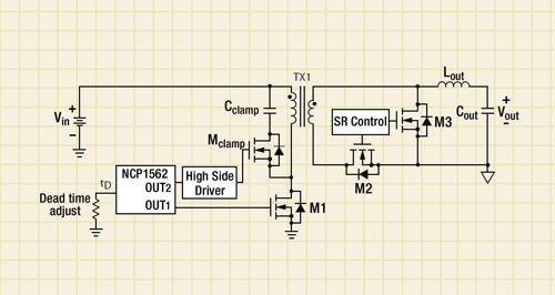
Fig. 4. The active-clamp forward topology, as shown in ON Semiconductor’s NCP1562 controller, is a soft-switching technology.
Advanced ICs from vendors such as ON Semiconductor are greatly easing the implementation of this topology, and the adoption of this topology in higher-volume applications will lead to lower costs of all the components involved. However, it does require higher-voltage-rated switches than the 2-Sw forward or half-bridge converters.
LLC resonant half-bridge
The LLC resonant topology (see Fig. 5 ) is best suited for applications that require high output voltages such as LCD and plasma TVs. Like the active-clamp topology, this is also a soft-switching topology that can achieve very high efficiencies due to very low switching losses. It also requires no output inductor, thereby lowering its cost and size, and, due to the half-bridge configuration, stresses on its primary side components are reduced.
On the other hand, this topology also presents some drawbacks, including much more complex magnetics design. Other limitations are a variable frequency and high ripple current in the output capacitor. This topology is also harder to design for wide input voltage ranges.
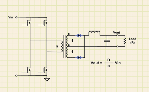
Fig. 5. The LLC resonant half-bridge topology is best suited for applications that require high output voltages.
Comparisons
While it is impossible to prescribe a single topology as a solution for all applications, interesting conclusions can be reached by seeing how each topology can be optimized for an application. Some summary differences in these designs:
• Primary switches: For an input-voltage range of 300-400 Vdc, the primary peak currents are the lowest for the active-clamp converter topology. The 1-Sw and 2-Sw forward have similar rms current to the active clamp, but have more conduction losses due to MOSFET voltage ratings.
• The dc secondary rectifier voltage stress is the lowest for the resonant HB converter, followed by active clamp and then by 1-Sw and 2-Sw forward converters. The stress is further increased in the traditional topologies because of the switching spikes.
• The resonant HB offers apparent simplicity of magnetics, by eliminating the output inductor, however, the transformer design is significantly more challenging. The output inductor size is about 13% smaller for the active-clamp converter compared to the traditional forward converters, at the same switching frequency.
• The output capacitor current ripple is the highest for the resonant HB converter due to absence of an output inductor.
• The switching frequency can be pushed higher (200 to 300 kHz) for the active-clamp forward converter, while it is recommended to be below 150 kHz for the hard-switching topologies. The resonant HB is a variable frequency converter, and typically, the minimum frequency (full load, low line) is set at 60 to 70 kHz. The maximum frequency can be several-hundred kilohertz for high-line light load operation.
Advertisement
Learn more about ON Semiconductor


