Here’s how to use the digital amplifier for power levels, channel counts, and audio performance
BY KEVIN BELNAP
Texas Instruments
Dallas, TX
http://www.ti.com
One of the most consistent trends that face audio engineers worldwide is the acceleration of the design cycle. Today’s consumer market moves extremely fast and demands that manufacturers respond quickly or face a rapidly shrinking market window. For example, the DVD player had the fastest market penetration rate in history, forcing companies to shorten time to market to stay competitive. To survive in this market environment requires tightly coupled design, testing, and production for manufacturers of consumer electronics.
For designers using the digital amplifier, this trend poses significant challenges. When the digital amp was introduced to the market, it heralded a new age of high efficiency, good audio quality, and configurability and was rapidly adopted by consumer audio companies that wanted to take advantage of these capabilities.
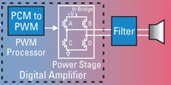
Typically, the digital amplifier has a two-stage architecturea pulse-width modulation (PWM) processor followed by the power stage as shown in Fig. 1. The 3.3-V PWM processor accepts the 3.3-V audio data, performs audio processing, and then converts the pulse-code modulated (PCM) data into PWM data. The PWM processor is typically controlled through IIC to change volume, tone controls, or other audio-processing functions like EQ. The ability to easily control the audio processing is a big benefit, but comes at a cost of increased complexity in the system microcontroller firmware.
Since a digital amplifier generally requires more firmware development than a traditional analog amplifier, it is critical that design reuse is employed. The power stage takes the 3.3-V PWM signal, translates it to a higher voltage, and applies it to the speaker through the MOSFET H-bridge and second-order LC filter.

Fig. 1. Typically, the digital amp is composed of a PWM processor followed by a power stage H-bridge.
Power levels
For most consumer audio companies, it is typical to have almost identical models that differ only in the industrial design and the number of channels and/or power output per channel. The following might be typical of a manufacturer’s product line:
| Configuration | Power levels |
|
5.1 |
100Wx5, 200Wx1 |
|
5.1 |
50Wx5, 100Wx1 |
|
6.1 |
100Wx6, 200Wx1 |
|
2.0 |
100Wx2 |
|
2.1 |
100Wx2, 200Wx1 |
|
2.1 |
50Wx2, 100Wx1 |
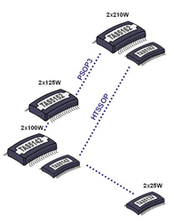
The power output of a digital amplifier is directly proportional to the square of the voltage on the power stage H-bridge. This means that an engineer can simply lower or raise the H-bridge voltage to meet the lower power model’s power requirement. The drawback to using this approach is that a power stage with a 100-W output rating will be used for a 50 W system, which is not cost-effective. A better way to solve this problem is shown in Fig. 2. Each of the power stages are pin-for-pin compatible. To meet a particular power per channel requirement, it is a simple matter of making a bill of materials (BOM) option.

Fig. 2. Power stages that are pin-for-pin compatible is a better approach in meeting lower power model’s power requirement.
Channel counts
The next challenge is to design different channel counts. One way to solve this is to use stuffing options and not populate some of the chips. However, again, this is not a cost optimal solution especially for the 2.1 channel case where one stereo channel will be unused.
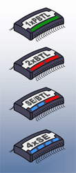
All power stages shown in Fig. 2 can be put in one of the modes shown in Fig. 3. Bridge-tied load (BTL) is the normal configuration for most stereo power stages where the speaker is connected between the two MOSFET half-bridges shown in Fig. 1.

Fig. 3. Shown are various combinations of power stages and channel modes
Parallel bridge-tied load (PBTL) is when both outputs from a stereo BTL power stage output drive a single speaker and the power output is therefore doubled. Single-ended (SE) refers to when each speaker is driven by a single MOSFET half-bridge. The channel count is doubled in SE mode but the power is cut by about 25%. ”Split mode” means that two channels are single ended (SE) and one is BTL.
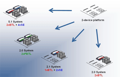
This gives a lot of flexibility to designers. As Fig. 4 shows, one board can be used across four different channel counts. Adding the different power levels shown in Fig. 2, this is a total of 16 different models that can be manufactured from a single PCB.

Fig. 4. New designs offer flexibility when adding different power levels on a single PCB.
Audio performance
In addition to power levels and channel counts, a third dimension of configurability is often required by the consumer marketaudio quality, typically measured by the signal-to-noise ratio (SNR) and/or dynamic range. With TI’s digital amplifiers, for example,SNR is determined solely by the PWM processor so differentiating products by audio performance can be as simple as using stuffing options.
To extend the audio performance even further, another option is available to audio designers. As mentioned previously, the power output of a digital amplifier is directly proportional to the voltage level on the H-bridge in the power stage. This means that if the H-bridge voltage can be varied, it can essentially become a volume control. One example of this is to vary the H-bridge voltage according to the following table for the first 24 dB of volume control.
Table 1. H-bridge voltage for the first 24 dB of volume control
| H-bridge voltage (dBFS) | Volume (dB) |
|
50 |
0 |
|
25 |
-6 |
|
12.5 |
-12 |
|
6.25 |
-18 |
|
3.125 |
-24 |
After the H-bridge reaches –24 dB, it is best to switch over to digital attenuation for further reductions in volume as it will be difficult to control the power supply voltage to the precision needed below this point. Note that above 0 dB, digital gain must be used. This algorithm is not difficult to program into the system microcontroller. However, it is hard-coded as an enable option in some PWM processors and is called power supply volume controlled (PSVC). A power supply must be designed to vary the output voltage. It also must have good stability at these varied voltages. An analog output from the PWM processor can be used to control the power supply output level. All that is needed from the microcontroller is the absolute volume level (in dB) and the PWM processor will automatically calculate the correct power supply level and digital gain/attenuation setting.
In a system with PSVC, the dynamic rangedefined as the ratio of the minimum signal to the maximum signal a system can supplyis extended by the same amount the power supply is changed. Note that in the above example, the power supply is varied by 24 dB, and if the PWM processor has 110 dB of dynamic range the system dynamic range would be 110 dB + 24 dB = 134 dB. This is outstanding dynamic rangeequivalent to the some of the best DACs available in the market today.
The digital amplifier is a tremendously versatile and configurable product. With a little design and up-front planning, it can be used to speed designs and enable design reuse. It has largely lived up to its promise of enabling these dimensions of configurability (power, channel counts, and audio performance), and is being adopted in an expanding number of products and markets. Both the designer and manufacturer benefit from design reuse as more products can be produced with a single PCB.
Advertisement
Learn more about Texas Instruments


