Selecting the right amp for thermocouple apps
The designer needs to know key parameters
BY KEVIN TRETTER
Microchip Technology
Chandler, AZ
http://www.microchip.com
Thermocouples are one type of sensor commonly used to measure temperature. Thermocouples are generally inexpensive, robust, have a fast response time and can work over an extremely wide range of temperatures, which makes them ideal for use in extreme conditions. However, the signal conditioning designed to work with thermocouples must also account for harsh environmental conditions. When selecting an amplifier to provide signal conditioning, it is critical to ensure that the amplifier has low input-bias current, low voltage offset, low drift and enough open-loop gain to ensure optimal system performance.
Background
Sensors are used to measure a variety of different physical conditions, the most common of which is temperature. Temperature measurement is found in a wide range of applications, from industrial applications such as HVAC units and industrial control, to consumer products such as computers and stereo equipment. Consequently, there are many different types of sensors that can be used to measure temperature, depending upon the application.
One type of sensor commonly used to measure temperature is the thermocouple. Thermocouples are composed of two different metals soldered together on one end. Any difference in temperature between the two ends of the thermocouple causes a voltage differential. This differential changes as a function of temperature. Any junction of two dissimilar metals forms a thermocouple (or thermojunction), but some combinations of metals work better than others. There are a variety of different types of thermocouples available, each having its own set of advantages and disadvantages.
Regardless of type, thermocouples generally have a wide operating temperature range, fast response time and are very robust, making them well suited for extreme conditions such as cryogenics and other industrial applications. However, thermocouples also possess some disadvantages. For example, the voltage change induced across a thermocouple is very small. Most thermocouples output only 50 mV to 80 mV across their entire operating temperature range, which could span 800°C or more!

Need for signal conditioning
As mentioned above, the voltage change across a thermocouple can be very small, especially if the sensor is operating over a relatively narrow temperature range. Proper signal-conditioning circuitry is crucial to accurately measuring temperature.
One key component of this signal-conditioning circuitry is the amplifier. An amplifier is used to provide voltage gain and filtering, as well as to buffer the signal coming from the thermocouple before it is converted to a digital signal. There are several key parameters that designers should consider when selecting an amplifier for a thermocouple application.
Input bias current overview
All amplifiers have a specification called “input bias current.” This is the amount of current flow into an amplifier’s inputs that is required to bias the input transistors. This current can be thought of as a leakage current, but is often referred to as bias current when it is on the inputs of an amplifier. This bias current can range from picoamperes to hundreds of nanoamperes. Amplifiers with a CMOS input stage generally have less bias current, when compared to amplifiers with bipolar input transistors.
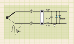
Bias current is a critical specification to consider when using thermocouples or other high-impedance sensors. As the bias current flows through this high resistance, a voltage error is created. If thermocouples are simply two pieces of medal soldered together, why is the impedance high? As mentioned earlier, thermocouples can be located in very harsh environments, and are prone to picking up large noise spikes, such as ac-motor starters, or to shorting out in an electric furnace. This noise can potentially damage the circuitry connected to the thermocouple. Therefore, it is desirable to place resistors in series with the thermocouple in order to form a filter, as shown in Fig. 1.
In this example, the resistors are combined with the capacitor to create a low-pass filter. The resistors also offer some protection to the rest of the circuitry. Large value resistors are desirable to increase ESD protection and noise filtering. A larger resistor means that the same low-pass filter corner can be maintained with a smaller capacitor, which helps to minimize design size and cost. However, the amplifier’s bias current will flow through these resistors, which causes a voltage error in the measurement. By selecting an amplifier with a low bias current, this error source can be minimized.
Input offset voltage overview
Another important amplifier specification is input offset voltage. As the name implies, this specification is the amplifier’s voltage difference between the inverting and non-inverting inputs. This voltage offset is dependent upon the amplifier’s topology and can range from microvolts to millivolts in magnitude.
As mentioned earlier, the voltage induced across a thermocouple as a function of temperature is on the order of millivolts. An amplifier offset voltage that is also in the range of a few millivolts will adversely affect the temperature measurement. Some systems may implement system calibration in order to eliminate the initial offset. If not, a low offset, high-precision amplifier (such as the MCP603X) is required.

Fig 1. Resistors in series with the thermocouple are needed to form a filter/protection circuit.
Voltage offset drift overview
Like all electrical components, amplifiers behave differently over temperature. This is certainly true of the amplifier’s voltage offset. As noted above, the voltage offset is a source of error, and as the offset drifts over temperature, this error correlates to the temperature.
Even a high-precision amplifier, such as the MCP603X, is susceptible to temperature drift. This error source can be minimized by selecting a low-drift amplifier, such as an amplifier with an auto-zero based topology, or by implementing periodic system calibrations to calibrate out the offset and drift.
Open-loop gain overview
To increase the resolution of the temperature measurement, the amplifier may be configured to amplify the voltage induced across the thermocouple prior to digital conversion. Due to the small input signal generated by the thermocouple, this amplification may be 100 to 500 times.
An amplifier must have enough open-loop gain to not only provide the required amplification, but also to maintain enough linearity to avoid limiting the overall system performance. For example, if an amplifier has an open-loop gain of 100 dB and is configured for a gain of 200 (46 dB), this leaves only 54 dB of open-loop gain margin to ensure linearity, or about one part in 500. Depending upon the application, this level of performance may not be acceptable. ■


Advertisement
Learn more about Microchip Technology


