Selecting high-speed backplane interconnects
Some information to help you navigate the channel as speed, bandwidth, and port density continue to increase
BY BRIAN HAUGE and GOURGEN OGANESSYAN
Molex
Lisle, IL
http://molex.com
Design engineers are continually looking to meet the demand for increased speed, bandwidth, and port density in various communications applications. To keep pace, backplane connector manufacturers have begun offering innovative designs to support these needs. Some OEMs are using newly emerging architectures such as orthogonal systems—both hybrid and direct-connect (no midplane)—to improve their channel performance and lower the overall costs associated with increasingly complex midplane designs.

Right-angle-to-vertical
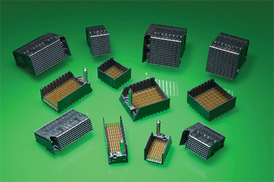
Right-angle-to-vertical backplane interconnect solutions facilitate a cross-connection between all system data points. These traditional backplane connector products are designed for use in industry-standard rack sizes, making them a common choice in system design.
Almost all backplane connector solutions allow for blind mating of daughtercards into the chassis and are sequenced properly for gross alignment, keying, power, and signal delivery—all of which allow OEMs field upgradeability and scalability options for their systems. Most backplane connector solutions support the many different industry-standard slot widths that allow for multiple daughtercard sizes.
They also typically offer linear signal and power scalability via end-to-end stackable monoblocks and/or waferized systems to support the many different daughtercard applications. Overall, these traditional solutions support a wide range of applications, including data communications, telecommunications, military, and medical equipment.
Primary requirements to consider when choosing a backplane interconnect solution are high-speed data rates (single-ended or differential), low-speed (single-ended) signals, power and gross-alignment/guidance requirements, as well as the total dimensional envelope (height, length, depth) available for the connectors. The biggest system-level challenges are typically space, PCB thickness/aspect ratio limitations, PCB routing limitations, power management and cooling/airflow.
While these solutions accommodate virtually any type of system design, higher port densities drive the need for more signal lines routed across the backplane. This drives a heightened potential for signal integrity degradation, spacing issues, and layer-count increases, ultimately ending with additional costs.
In turn, many connector manufacturers are challenged with delivering high-speed, high-performance connector solutions that occupy less space and have lower profiles to accommodate airflow requirements at a lower cost. With material costs continually rising, it is challenging for connector manufacturers to deliver increased capabilities at a lower price, particularly with traditional backplane interconnect solutions.
Orthogonal midplanes
Orthogonal backplane solutions are quickly emerging in a number of traditional server, switch, and storage applications. Now that the industry has evolved into high-speed differential architectures, connector solutions are needed to facilitate the transition of differential pairs from daughtercard-to-daughtercard through the midplane, while still maintaining the channel’s signal integrity performance.
These orthogonal solutions are unique because they eliminate the need for signal traces routed through the midplane, lowering cost and improving signal integrity performance. The shorter channel lengths demonstrate less attenuation, and with the midplane via stubs removed, there is less opportunity for energy reflections that result in lower crosstalk. However, higher port density at a lower applied cost is the single largest benefit of a true orthogonal architecture.
Airflow is the biggest challenge when working with orthogonal interconnects. It can be difficult to cool a system that has daughtercards rotated 90 on one side of the midplane.
One solution is direct-connect orthogonal connectors, which completely eliminate the midplane to further improve the system’s signal integrity performance and airflow. Additionally, transitioning from a traditional system to a pure orthogonal system can pose some backward compatibility and legacy obstacles.
Coplanar/mezzanine devices
Coplanar and mezzanine solutions are typically used for I/O flexibility and backward compatibility, memory expansion, and core processing expansion. In most backplane product families, these solutions feature the same mechanical and electrical properties found in traditional backplane connectors, including common separable interfaces, compliant pins, guidance, and power options.
In mezzanine solutions, airflow and heat sinks typically dictate the mated-connector stack heights, posing some challenges for connector manufacturers. Due to the constantly changing thermal dynamics of systems, different stack heights are commonly required across different systems.
In coplanar solutions, the internal and external I/Os used on the daughtercards typically dictate signal performance requirements, as well as space available for coplanar connectors. Most backplane connector product families offer right-angle male options that leverage the mating interfaces; PCB footprint/attach methodology; and mating sequences to allow electrical and mechanical continuity across the entire system.
True channel performance
Despite the care taken in optimizing a connector’s electrical parameters, system-level performance is determined by the entire channel. PCB interface (vias or SMT attach); chip package and BGA attach; board traces; and dc blocking caps all influence channel performance.
This results in a need to quantify the channel behavior. Several industry forums and standards committees have tackled this problem, and a couple of distinct solutions are available.

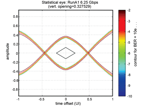
Fig. 1. Mathematical algorithms such as StatEye can assist in specifying channel compliance.
The Optical Internetworking Forum’s Common Electrical Interface (CEI) implementation agreements have chosen a methodology called StatEye to specify channel compliance (see Fig. 1 ). StatEye is a mathematical algorithm in Matlab that provides probability contours for eye diagram openings corresponding to different Bit Error Rate (BER) magnitudes.
The software stimulates a given channel and uses a specified reference transmitter (with pre- or post-emphasis) and receiver models. If the resultant eye contours do not interfere with a given mask, then the channel is deemed compliant.
The IEEE 802.3 (Ethernet) working group took a different approach for its 802.3ap 10G Backplane Ethernet standard, which specifies limit lines for channel transfer functions, as well as parameters including insertion-loss ripple and insertion-loss-to-crosstalk ratio (ICR). ■
For more on high-speed backplane interconnects, visit http://electronicproducts-com-develop.go-vip.net/packaging.asp.
Advertisement
Learn more about Molex


