Resistor type, spectral content, and transmission-line length are important aspects to proper design
BY JERRY SEAMS
IRC Advanced Film Div.
Corpus Christi, TX
http://www.irctt.com
A resistor’s purpose in life is to convert electrical energy into heat. That’s all it does. Period. But this humble singular purpose can be applied to countless applications, including the termination of high-speed transmission lines.
Why terminate?
When electrical current flows through a resistor, some or all of the energy in that electrical current is converted to heat and is lost forever. We call this electrical-to-heat conversion electrical “loss.” When electrical information is transferred from one physical location to another, transmission lines are often used as the high-speed conduits of this information.
Resistive terminations make use of their ability to convert electrical energy into heat to prevent reflections. The type of resistor, spectral content of the signal, and the length of the transmission line are all important aspects of proper transmission-line design and termination. Thin-film resistors designed with minimal parasitic capacitance and inductance make the best resistive transmission-line terminators.
Ideal transmission lines are considered to be lossless, meaning none of the energy in a signal travelling down the transmission line is converted to heat and the energy is not lost. If the energy is not lost or converted to heat, it remains in the transmission line to reflect back and forth, interfering with other signals on the line. Termination resistors cure reflected energy issues on transmission lines by converting the electrical energy into heat.
When to terminate
Knowing when to terminate a transmission line is a function of the frequency/wavelength of the signal and the length of the transmission line. For signals carrying a maximum spectral content of 10 MHz, a 3-m or shorter transmission line may be designed without a terminator. The wavelength of the signal is long compared to the length of the line itself.
But when the wavelength of the signal becomes small compared to the transmission-line length, a terminator is required to prevent the signal from reflecting back toward the source and interfering with forward traveling signals. A signal with significant spectral content to 10 GHz needs to be terminated for any line longer than 3 mm!
How to terminate
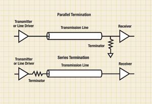
Basic transmission-line termination is performed using one of two methods: parallel or series. Parallel termination connects a resistor between the transmission line and ground near the end of the transmission line. Series termination connects a resistor in series with the signal path near the beginning of the transmission line (see Fig. 1 )

Fig. 1. Basic termination is accomplished with one of two methods: parallel or series.
Resistive termination requires a resistor value that matches the characteristic impedance of the transmission line. Most transmission lines are designed with either a 50- or 75-Ω characteristic impedance. The termination resistance must be matched to the transmission-line characteristic impedance to prevent the electrical energy in the signal from causing a reflection at the end of the line.
If the resistor is perfectly matched to the characteristic impedance of the transmission line, all the energy in the signal will be dissipated as heat in the termination resistor. With no energy remaining, there is no signal to reflect backwards down the line.
What to use?
What kind of resistor makes a good terminator from dc to high frequency? An ideal resistor would contain no parasitic capacitance or inductance to interfere with its purpose of converting electrical energy into heat.
We do not live in an ideal world. Any resistor package will have some reactive parasitics. The question is, how large are the parasitics and how much do they interfere with an ideal transmission-line termination? Return loss and VSWR are two measures of the reflection due to a non-ideal terminating resistor.
Of course, every design has its own set of goals and reflection limits, but normally less than 10% reflection at the maximum design frequency is acceptable. This relates to VSWR measurements of less than 1.2 or a return loss measurement of less than 20 dB.
There are basically two different types of high speed transmission lines: analog (RF/microwave) and digital. Although the physics and engineering principles are the same for both types, the resistive terminators used in each can be quite different.
RF / microwave applications
RF and microwave applications typically use just a few termination resistors. An example would be the RF transmit and receive lines in a wireless communications application. Termination resistors are usually discretes—often chip resistors—since there are few lines to terminate in the application.
High-speed digital applications often use arrays of resistors in a single package. Digital bus widths continue to swell to 32, 64, and 128 bits and beyond. At digital data rates in the Gbit/s range for each bus line, transmission lines and termination resistors with good high-frequency performance are mandatory.
Since there are so many termination resistors required (usually in a limited space), small size and high element densities are also required. Reflected energy in the transmission line is detrimental to the health of high-speed and high-frequency communication systems.
Reflected signals interfere with other signals travelling down the transmission line causing interference and signal integrity problems. Minimization of reflected signals is a priority of good high-frequency/high-speed transmission line design. ■
For more on RF terminations, visit http://electronicproducts-com-develop.go-vip.net/passives.asp
Advertisement
Learn more about TT electronics IRC


