Battling single-event upsets in programmable logic
Technology choices to reduce SEUs caused by cosmic rays
BY CHRIS TENNANT
NEC Electronics America
Santa Clara, CA
http://www.am.necel.com
You take your seat, the lights dim and you set your expectations on watching a great “B” movie featuring state-of-the-art electronic wizardry and a story about hidden evil spawned by, what else, exposure to radiation. Unbeknownst to the townspeople in the movie, something insidious lurks, all the while growing. They finally recognize it and spend the rest of the movie trying to thwart it.
You return to your job and work madly in the lab designing the next great electronic product. There’s something happening underneath the surface, however—a potential threat that can wreak havoc. The threat to memory and programmable logic from cosmic rays are well known to engineers, but a review of these phenomena is a good idea. When a ray hits a molecule in the atmosphere, the molecule is broken into subatomic particles that, in turn, break other molecules that shower the earth.
Those neutron particles pass through buildings, people, and semiconductors. When one strikes a configuration bit of a semiconductor, the device’s program or circuit can be altered, causing the device to operate with the corrupted program until it is either restarted or changed. This is known as a single-event upset (SEU) and cosmic ray radiation is just one of its causes.
The severity of a bit change is random. For end customers, effects can range from going unnoticed to causing downtime and/or consequential damages, all of which can lead to a call to the service department.
Although the wayward design can usually be fixed with a reset, new problems may appear a short time later. Frequently reloading (scrubbing) the configuration memory does not eliminate the problems, and side effects can still propagate into the neighboring logic, software and data. While engineers can add error correction and error tolerance circuitry to their designs, it is difficult to design immunity into the underlying configuration memory—and that’s where most of the errors occur.

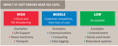
The significance of an SEU is categorized into three types.
FIT rates
The industry-standard reporting of failures in time is the FIT rate. An FIT is one failure in one billion (109) hours.
The FIT rate for a given device can vary by process generation, by the number of configuration bits, and by the way the bits were designed. External factors such as altitude and variations due to latitude also play a role. For example, the city of Denver receives 3.75 times higher neutron flux than San Diego. Other factors also include time of day and solar conditions. The FIT rate is supposed to lump all effects together, including all sources of soft errors, but it is important to know all of the conditions when selecting a device.
The FIT rate allows a designer to calculate total exposure. For example, if a product has a 400-FIT soft-error rate and 100,000 units of the product are currently in operation, then an average of one soft error would occur in the field every 25 hours.
Based on these numbers, one can see how companies with more FITs per product or more installed products (or both) can have many soft errors per day around the world. It is when this rate becomes unacceptable that a company must decide where they need to make improvements.
Existing designs: Prioritize where to improve
The urgency to reduce soft errors can be divided into three categories. Highest priority is given to products that endanger life, limb and property. Second priority is given to products that can damage the company’s reputation or that cause an unacceptably high number of issues for customers. Key customers who buy or distribute more of your products will observe higher failure rates simply because there are more failures occurring and the same people are seeing them. All other cases are in the low-priority category because they are less likely to happen or are insignificant when they do. Beyond individual products, the question is whether the aggregate rate for all products is acceptable.
Those are the short-term measures. There is also the long-term program: the implementation of semiconductor solutions that can help to protect your designs from this unseen nemesis at the start of the project.
Understanding technology choices
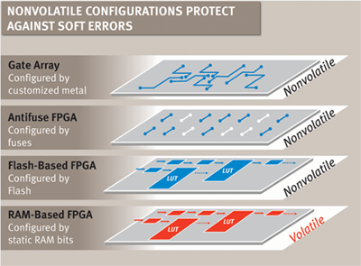
From a chip perspective, there are many technology choices that can be made to address the issue of SEUs. For custom designs where a short turnaround time is critical, device options include antifuse or flash-based FPGAs, SRAM-based FPGAs, and gate arrays.
In the case of antifuse- and flash-based FPGAs, recent research has shown that the devices are not susceptible to configuration errors due to neutron effects. However, RAM devices implemented by the designer are volatile and therefore susceptible to soft errors. The designer must determine whether the soft-error rate is acceptable.

Options exist for reduction of the threat from cosmic rays.
Most FPGAs used today are SRAM based, offering higher densities and performance than their nonvolatile counterparts, but with little protection against SEUs. SRAM-based FPGAs store configuration data in SRAM cells. Depending on the density and process, the FIT rate for these devices can range up to thousands of FITs, far above acceptable norms.
One technique designers can use to ensure higher reliability in SRAM-based FPGAs is triple module redundancy (TMR). In this technique, three identical devices compute the same data in parallel and output the results into majority voting logic. The failure of one device is discarded, assuming that the other two operated correctly. In practice, however, few designers can afford the increased board area, power overhead, and added cost. And, implementing this technique can be very time consuming.
Gate arrays are hardwired with customized metal interconnects and have no configuration memory to be corrupted. The memory implemented by the design still has a soft-error rate that varies by process family. This rate is low, less than 0.2 FIT/Kbit of RAM, for most families. A typical gate array will meet higher-performance goals and draw less power than an FPGA while providing a piece price advantage.
The mask charge for a 1,000 LUT gate array design (around 100K FPGA “system gates”) is about $10,000 , and unit prices are available under $1. For example, the NEC Electronics uPD65880 CMOS-N5 gate array in a 44-pin LQFP package has 2,937 usable ASIC gates and costs $0.85 each for 100,000 quantity orders. And, it takes only two weeks these days to design a gate array, with another 1.5 weeks to ship samples.
The hardwired architecture of a gate array enables high performance, less noise, low power, low leakage, low inrush currents, high design security and fast startup times of less than 1 ms.
It sounds like a familiar action-thriller. You made the world a better place with the great innovations you designed. But then, malevolent forces (Hollywood talk) from outer space exploited the vulnerability, threatening to undermine everything. You had to respond before it was too late! Your plan rapidly improved the soft-error immunity of your products using the single-event-upset immune technologies available. It was your cool, calculated approach that saved the day. ■
For more on programmable logic, visit http://electronicproducts-com-develop.go-vip.net/digital.asp.
Advertisement
Learn more about NEC Electronics America


