Communication protocols for lighting control
Electronic control of lighting can achieve significant energy savings
BY STEVE BOWLING
Microchip Technology
Chandler, AZ
http://www.microchip.com
Electronic control of lighting is one of the more significant ways that we can reduce global energy consumption. In the U.S., commercial and residential lighting applications consume 22% of the total energy generated. Significant savings can be achieved, especially when dimmable lamp technology is applied in large commercial applications.
Dimming-system applications require a communications interface to convey information to the fixture. One common method in use is 0 to 10-V analog control. However, it can get cumbersome to setup and manage if there are many fixtures.
Digital lighting control
Using a digital control system can relieve some of the analog complications by including lighting fixtures on a common, addressable network. The low cost of MCU technology has made it very easy to embed a digital protocol into an application. There are many wired and wireless choices that could be applied to a lighting-control application. So which one to choose?
First, the designer has a choice of medium for the protocol — wired or wireless? If wired, should we use twisted-pair wiring or power lines? If wireless, which frequency band should we select? For both wired and wireless installations, what is the maximum communication distance?
The application layer of the protocol must be considered. How many fixtures can we communicate with? Is there a command set defined for lighting? How will fixtures be added or removed from the network, and how is the address of each fixture determined? What will each fixture do after a loss of communication, or after power interruption? How easy will it be for a lighting installer to setup and configure the control system?
Widely implemented protocols such as TCP/IP or IEEE 802.11 could be used, but the amount of data that needs to be conveyed to each fixture is minimal and infrequent. We just need to send an ON, OFF, or dimming-level message every now and then. So, it would be wise to select a simple protocol to ease the requirements for the MCU in each fixture.
So, let’s look at two protocols that might be appropriate for lighting-control. The first is Digital Addressable Lighting Interface (DALI), a protocol defined in the IEC60929 specification that defines performance specifications for electronic fluorescent ballasts.
The DALI networking method
The DALI specification defines a constant-current bus that operates at a maximum of 250 mA and a nominal 16 V. Each device sends data on the bus by pulling the bus low (sinking current) through an optoisolator circuit. The wiring can be located inside or outside of conduits and the connections are polarity independent, making it easy for an installer. All fixtures are wired together using either a star or daisy-chain connection and each fixture is supplied with unswitched ac power.
The DALI protocol is very simple, but has a powerful command set designed specifically for lighting installations. The data is transferred using a Manchester format at 1,200 bits/s—fast enough for this application. The basic protocol definition includes a single master device (controller) and up to 64 controlled devices (ballasts). The master sends out a 16-bit command or request. The ballast device can optionally reply with an 8-bit response. A ballast device cannot send data on the bus unless it is requested by a controller device.
Controller devices can include control panels, switches, light sensors, occupancy sensors, and so on. Each controller can send messages directly to a ballast device or to another controller. For example, an occupancy sensor (a controller device) might want to send a message to a master control panel to indicate that there is activity in the room.
Any lighting control system needs a way to set up the node addresses and locations through a central computer, but DALI does not need any settings to be made during installation. The nodes can be hooked up in any order. The command set includes a method to automatically detect, identify, and assign an address to each ballast device on the network.
You might think that the ability to control 64 ballast devices is somewhat limited, but this limitation is what keeps the software overhead and hardware requirements very low. The full protocol can be implemented on a very inexpensive 8-bit MCU with less than 8 Kbytes of program storage and no special communications peripherals.
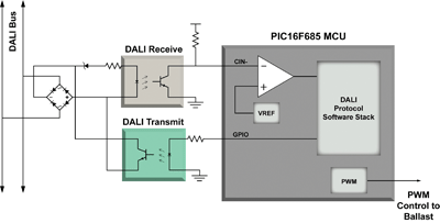
A typical implementation for a ballast device is shown in Fig. 1 . The 20-pin 8-bit MCU has a comparator for conditioning the input signal and a PWM that controls the dimming level of the ballast. This signal can be filtered, if needed, to provide a control voltage to the ballast power circuit.

Fig. 1. The DALI ballast interface has optocoupler-isolated I/O.
The ZigBee wireless solution
There has been a lot of buzz lately about the ZigBee wireless communication protocol. ZigBee is actually a software layer that operates on top of another wireless protocol defined by the IEEE 802.15.4 specification.
IEEE 802.15.4 defines the physical layer and media access layer for low-data-rate wireless communication over multiple frequency bands. The most common frequency band is 2.4 GHz, with a maximum data rate of 250 Kbits/s.
The maximum communication distance is dependent on the physical environment, but distances up to 250 ft are possible. IEEE 802.15.4 also defines a full-function device (FFD) and a reduced-function device (RFD). FFDs are intended to have continuous power and to be available on the network at all times. An RFD allows standby operation for battery-operated nodes that require low power consumption. A higher-level protocol, such as ZigBee, is used on top of the IEEE 802.15.4 specification to provide the application functions.
The ZigBee protocol provides the ability to create a self-organizing low-data-rate mesh network with up to 65,536 nodes. There are different types of ZigBee nodes. Every network has one coordinator, which contains information about all devices on the network, forms the network, and allocates addresses to end devices. End devices receive control inputs and provide status information. Devices on the network can optionally function as a router, which extends the maximum communication distance.
One of the primary advantages of ZigBee is the assurance of interoperability with other devices. All ZigBee products must be tested and certified, and there are standard control profiles, including one for lighting.
These profiles define a basic data structure for the application, but there is no command set and it is up to the developer to determine how the application will manipulate that data. For example, the ZigBee lighting profile includes a table of standard variables that hold the status of light-level sensors, occupancy sensors, the dimming level of a fixture, and so on.
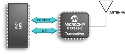
A typical ZigBee network node (see Fig. 2) consists of a 2.4-GHz 802.15.4 transceiver and an MCU. The type of ZigBee node that is implemented will determine the code space required for the protocol stack, which range from 20 Kbytes for an RFD end device to 40 Kbytes for a full-function coordinator.

Fig. 2. A typical ZigBee node has a 2.4-GHz 802.15.4 transceiver and an MCU.
Compared to the DALI protocol, the ZigBee stack requires a greater electronics cost at each fixture. A larger MCU with more program memory and an 802.15.4 transceiver device are required. Additional software will be required to process lighting commands and requests for status information. However, this cost must be balanced against the ease-of-installation benefit.
If a full ZigBee protocol implementation adds too much cost in electronic components, other network protocols could be used on top of the IEEE 802.15.4 specification. One example is the MiWi protocol, which provides reduced network functionality and retains the ability to co-exist with ZigBee-compliant networks. It is also possible to implement simple point-to-point protocols, which require relatively little software overhead and would be appropriate for lighting-control applications. ■
Related Products: Lighting
Advertisement
Learn more about Microchip Technology


