Traditional mechanical potentiometers will be replaced, whenever possible, by automatic adjustments using these parts
BY FABIEN FRANC
Catalyst Semiconductor
Santa Clara, CA
http://www.catsemi.com
Some electronic applications need an in-system adjustment, either as a one-time calibration during manufacturing or to change a parameter during normal operation. These applications can include gain-setting amplifiers, voltage dividers, and current-setting resistors, to name a few. Resistor potentiometers, also called trimmer or mechanical potentiometers, have been used traditionally, but require manually tuning the wiper position with a screwdriver or other tool.
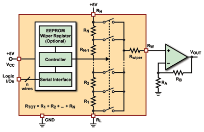
Today, digital potentiometers (digi-pots) can replace mechanical potentiometers, offering many benefits for in-system adjustment and calibration applications. They can be controlled through a digital interface and are driven directly by microcontrollers to provide higher accuracy and enable automatic adjustment without human intervention during manufacturing and calibration.
The typical process for making in-system adjustments involves generating a voltage reference or creating a variable resistor used in an amplifier gain-setting circuit. These two functions may be achieved with a digital potentiometer if the environment allows it.
The voltages of the controller supply (VCC ) and the potentiometer terminals (high RH , low RL , and wiper RW ) should be within the potentiometer voltage rating, for example, between 0 and 5 V. Most potentiometers are single supply, targeted for 5-V systems, but some specific devices can handle higher voltages, such as the Catalyst 16-V CAT5133.
Some “dual-supply” potentiometers handle both positive and negative supply voltages, for example 5 to +5 V on the potentiometer terminals. The wiper current should not exceed the maximum specified in the data sheet, for example 1 mA. Buffered wiper outputs can allow for a higher current, for example 3 mA.
Controlling wiper position
In the case of the variable resistor, the potentiometer becomes a two-terminal device (between RH -RW or RW -RL ). The end-to-end resistor (RTOT ) should meet the maximum targeted resistance value. Popular potentiometer resistor values are 10, 50, and 100 kΩ. The wiper resistance can become critical, especially when the wiper is positioned next to the high or low terminal, where values around 100 Ω are common. If we consider a total end-to-end resistance of only 1 kΩ, the wiper resistance becomes predominant, for example, a 100-Ω wiper resistance is already 10% of the total.

Fig. 1. A typical dig-pot can be controlled through a digital interface and is driven directly by microcontrollers to provide higher accuracy and enable automatic adjustment.
Wiper position control is achieved with a digital interface using a serial protocol involving two to four wires. The most basic protocol is often called “increment/decrement” or “up/down,” where two or three logic input signals control the wiper position by moving it one step at a time, either toward the high or the low terminal.
The up/down interface is a unidirectional bus, which allows the wiper to be moved, but cannot support actual reading of the wiper position. Other popular serial interfaces are the two-wire I2 C bus from Philips, as well as the SPI (Serial Peripheral Interface) bus developed by Motorola. These two protocols are bidirectional, which means they allow a microcontroller to write into the wiper register, causing the wiper to move, and also to read the wiper position.
Adjustment resolution
Depending on the resolution needed in the adjustment, potentiometers are offered with various total numbers of taps, generally between 32 and 256. When moving the wiper to the next tap position, the resistor increment is essentially constant for “linear” scale potentiometers and logarithmic, or a fixed decibel increment, for “logarithmic” scale potentiometers. Assuming the RL terminal is tied to ground, the voltage ratio for logarithmic potentiometers is:

In up/down potentiometers, the wiper position is moved one step at a time, while in other I2 C or SPI interface devices the wiper can be moved to any position. The wiper terminal is connected to each tap position using electronic switches.
Generally, when the wiper changes tap positions, the switches operate in a “make-before-break” mode where the new connection path is established before the previous contacts are opened. This ensures that the paths RW -RH and RW -RL never become open circuits (disconnected).
Automatic wiper position recall
Some types of equipment require a factory setting or calibration where the wiper position is set, retained in memory and recalled at each system power-up; for example, the backlight brightness setting in a display, or the audio volume setting in an MP3 player. For these applications, nonvolatile potentiometers offer the ability to store the current wiper position in an EEPROM register, where the position will be recalled when the device is turned on.
During power-up, the power-on reset (POR) circuit in a nonvolatile digital potentiometer restores the wiper position to the appropriate location when the supply voltage exceeds a determined threshold (about 2 V). After power-up, in volatile potentiometers the default wiper position is usually midscale, or halfway between the high and low terminals, and a microcontroller is required to restore the wiper position each time using data stored in its own memory.
The EEPROM cell is the same as the one used in standard serial EEPROM devices and, therefore supports the same 100-year data retention and one million write cycle minimum endurance. Digital potentiometers are usually manufactured in a low-power CMOS process and consume nearly zero current, well below 1 mA in standby mode, where the wiper position remains fixed, making them well suited for battery-powered applications.
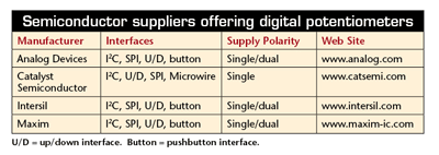
Semiconductor suppliers offering digital potentiometers

U/D = up/down interface. Button = pushbutton interface.
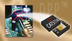
Several vendors offer potentiometers (see table ) in single, dual, and quad configurations where a common interface bus can address each potentiometer separately using instructions to write or read in the corresponding register. For example, dual potentiometers can be used in stereo audio devices. Many packages are available today from the tiny TDFN 8-lead 2 x 2.5 mm as shown in Fig. 2 , to SC70, SOT23, SOIC, or TSSOP, depending on the configuration.

Fig. 2. Nonvolatile dig-pot can be housed in the tiniest packages.
Real-world example: LED reading lamp
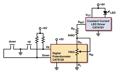
A digi-pot can be used to adjust the brightness of an LED reading lamp. A constant current LED driver controls the LED current using an external resistor. The potentiometer is configured as a variable resistor and placed in series with a discrete resistor Rs , as shown in Fig. 3. The maximum LED current is set by (Rs + Rwiper ), and the minimum LED current is set by (Rs + RTOT ).

Fig. 3. Show above is a digital potentiometer with pushbuttons for adjusting LED current.
In this example, the wiper position is controlled by two momentary pushbutton switches. Pressing down the switch generates a high-to-low transition on the input signal causing the wiper to move one step in the direction associated with that switch. Another solution is to use a single rocker switch, single-pole double-throw (SDPT) center-off three-position switch (momentary, off, momentary), with the common terminal connected to ground. ■
For more on digital potentiometers, visit http://www2.electronicproducts.com/AnalogMixICs.aspx.
Advertisement
Learn more about Catalyst Semiconductor


