Femto base stations bring wireless connectivity home
Analog front end for 3G brings challenges to the RF designer
BY THOMAS CAMERON and
PEADAR FORBES
Analog Devices, Norwood, MA
http://www.analog.com
Imagine a device that can provide high-quality cellular phone reception within your home, allowing you and your family unlimited voice and data usage for a low monthly fee. A femto base station, usually referred to as a femtocell, provides all that and more. This small wireless device, which improves local wireless coverage when placed in a home or office, is poised to dramatically change the wireless infrastructure landscape.
What is a femtocell?
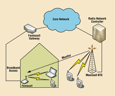
While traditional base stations provide wide area coverage, a femtocell (see Fig. 1 ) provides wireless coverage in a small area such as a residence. The femtocell routes mobile traffic to the network through the user’s broadband Internet connection, thus offloading traffic from the radio network. It improves the capacity of the network, while reducing backhaul, power, and maintenance costs for the operator.
The femtocell also lets operators compete for services in homes that have limited signal coverage. In exchange for a subsidized femtocell, the operator adds an additional fee to the customer’s monthly cellular plan.

Fig. 1. Femto base station compared to macro base station.
When in the femtocell zone, all mobile usage is covered under the home billing plan, allowing unlimited voice and data in the home without incurring large monthly bills. The proximity of the femtocell enables a high-quality link, while simultaneously reducing handset battery usage. The femtocell overcomes the limitation of 3G signals from the base station to penetrate walls, enabling high-speed access to mobile data services such as browsing the Internet, downloading music, and streaming video on the handset.
The femtocell, similar to a Wi-Fi router, is based on proven wireless infrastructure standards (UMTS, CDMA). Compatible with emerging standards, it provides an efficient, robust wireless link using operator-owned spectrum.
Compatibility with existing handsets makes the connection transparent to the user. Unlike a macrocell network, which aggregates tens or hundreds of base stations onto the core network, a femtocell gateway must manage thousands or even millions of femtocell nodes.
Unique challenges
Femtocells, which must provide the quality of service (QoS) expected from a base station at a cost similar to a handset, present unique challenges to the radio designer. The femtocell must provide both high-quality voice service and high-speed mobile data services (EVDO and HSPA) at a fraction of the cost of a macronode.
To meet these challenges, the femtocell design must take advantage of low-cost manufacturing techniques and highly integrated circuits that minimize calibration and test time. Femtocells reside in the home, so they must be small, low cost, and user installed.
Transmitting at low power — on the order of 100 mW —femtocells must be aware of the wireless environment to mitigate interference and meet regulatory requirements. 3G femtocells must monitor UMTS channels to detect base stations in the vicinity, as well as GSM channels to establish cells that might be appropriate for handover when a user leaves the femtocell zone.
Femtocell functions
The femtocell can be viewed as two distinct functions: an analog front end and a baseband processor. The front end, which is the topic of this article, converts the digital data stream into an RF signal in the transmit circuit, and vice versa in the receive chain.
The front-end design entails tradeoffs between integration and performance. Although discrete solutions can be tailored to provide the best performance, the cost would be prohibitive for a femtocell design. Conversely, a fully integrated solution may provide the lowest cost, but the performance may not be sufficient.
Inside a femtocell
Figure 2 illustrates a block diagram of a femtocell designed for local base station operation in UMTS band 1 as well as monitoring signals in the 850-, 900-, 1,800-, 1,900-, and 2,100-MHz bands.

Fig. 2. Femtocell analog front-end implementation based on an integrated solution.
On the transmit side, the digital baseband feeds a 12-bit parallel data stream to the mixed-signal front-end and converts it to an analog I/Q baseband signal. The baseband signal is converted to RF by the integrated radio transceiver, amplified by the RF driver amp gain stages, and sent to a duplexer. A power detector monitors the RF output. A single-pole, six-throw (SP6T) switch selects which transmit- or receive-monitoring chain is connected to the single antenna. This signal chain provides 13-dBm output power at the RF output connector, while meeting transmit ACLR specifications as defined in 3GPP standard TS25.104. The receive chain includes surface acoustic wave (SAW) filters and SPDT switches for monitoring the main path. The matching blocks consist of a simple series/shunt inductor for each receive port.
The integrated radio transceiver has three receiver input pins: one for band 1, and one each for high- and low band monitoring functions. The band-1 receive function may be switched between 1,960 MHz to receive the uplink signal and 2,140 MHz to monitor the downlink frequency.
The integrated radio transceiver downconverts and filters the selected RF signal to a baseband I/Q signal. The baseband signal is sampled by the mixed-signal front-end and converted to dual 12-bit parallel bit streams for the digital baseband.
This functional partition provides the designer with flexibility, ensures high performance in the signal chain, and allows the data converter’s speed and resolution to be chosen to fit the application’s requirements. This solution enables the designer to combine the analog front end with a commercially available baseband function, accelerating time to market of the femtocell design, while maintaining the benefit of future integration as the femtocell market matures. ■
For more on femtocells, visit http://www2.electronicproducts.com/AnalogMixICs.aspx.
Advertisement
Learn more about Analog Devices


