Active ORing solutions reduce power losses, size
You must understand the fundamental boundary conditions for your specific app
BY CARL SMITH
Picor, North Smithfield, RI
http://www.picorpower.com
An active ORing solution combines a power MOSFET and a controller IC. The MOSFET has an on-state resistance RDS(on) characteristic that, when multiplied by the square of the current through the device, creates power loss in the MOSFET.
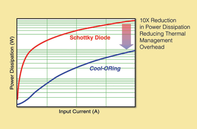
This loss can be up to 10 times lower than the power loss of a Schottky diode ORing solution for the equivalent current. That means an active ORing solution can be much smaller than a standard ORing diode solution because of its low power dissipation, and substantially reduced dependency on thermal management.
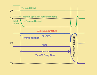
However, active ORing does have tradeoffs. A MOSFET, when it is turned on, allows current to flow in either direction through its channel. Because of this it is essential that the active ORing solution be very accurate and capable of extremely fast detection of reverse current fault conditions. Once the fault has been detected, the controller is required to turn off the MOSFET as fast as possible, and thus in turn isolate the input fault from the redundant bus and prevent any further reverse current.
A suitable solution
When attempting to select a suitable ORing solution, the key is to understand the fundamental boundary conditions for the specific application, then the choice of which type of ORing solution becomes clearer. Although this is not an exhaustive list, some typical boundary conditions are as follows:
Maximum ambient temperature rise in the system, where the power solution has to maintain reliable operation.Specific real-estate area allocated for the solution.Available thermal management (fans, heat sinks, PCB area, etc)Worse-case fault conditions (where response time and speed of the ORing solution are critical).
It’s worth starting with an analysis of a typical diode ORing solution versus a typical Active ORing solution in a specific application environment. The following analysis will be based on a 20-A load current where an expected maximum ambient temperature could be 70°C.
Typical Diode Power Dissipation (PD(diode) ): VF x IF = ~0.45 V x 20 A = 9 W
Active ORing Power Dissipation (PDFET ):
ID 2 x RDS(on) = 20 A2 x 1.5 mΩ = 0.6 W,
where 1.5 mΩ is a typical RDS(on) number taken from the Picor PI2121 Cool-ORing device.
If the maximum operating junction temperature of the devices are to be maintained at 125C, this will then dictate the required thermal management overhead.
TJ = Tamb + (PD x Rthj-a )
where,
TJ = Device Junction Temperature
Tamb = System Ambient Temperature
PD = Device Power Dissipation
Rthj-a = Thermal Resistance (junction-to-ambient)
The Rthj-a required to maintain the 125C junction temperature of the diode is around 6C/W
The Rthj-a required to maintain the 125C junction temperature of the MOSFET is around 92C/W.
The higher the Rthj-a number, the less dependency there is on thermal management overhead and the total cost of ownership will be reduced, making an active ORing solution very attractive. The benefits of active ORing usually mean that this is the best approach for providing the smallest solution, if real estate is of a premium. High-density system-in-a-package (SiP) products offer the best solution density, while providing added IC-to-FET optimizations to provide incremental electrical improvements. Discrete solutions using industry-standard packages have built-in limitations as far as component sizes, PCB spacing between components, and stray parasitics that hinder overall density and electrical performance.
Accurate sensing is required to determine the magnitude and polarity of the voltage across the MOSFET which is representative of current flow through the device. The reverse threshold will define the amount of reverse current through the MOSFET before a fault event is triggered, and the gate drive characteristics of the controller will determine the turn-off time of the MOSFET and thus the resultant peak reverse current through the MOSFET. The lower the threshold and higher the gate drive will ensure earlier detection and lower overall peak reverse current and ultimately reduced potential for any redundant bus voltage droops.
Active ORing solutions
Picor, for example, has a line of active ORing solutions (Cool-ORing Series) that combine a high-speed ORing MOSFET controller and a very low on-state resistance MOSFET in a high-density thermally enhanced land-grid-array (LGA) package. These solutions achieve as low as 1.5-mΩ typical on-state resistance while enabling up to 24 A of continuous load current over a wide range of operating temperature.
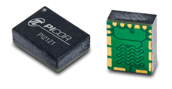
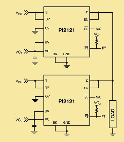
The LGA package is an extremely small 5 x 7-mm solution, which is thermally enhanced (see Fig. 1 ) and can be used in low-voltage, high-side (see Fig. 2 ) active ORing applications. The Cool-ORing solutions offer over 50% space savings versus conventional active ORing solutions. They enable low power loss (see Fig. 3 ) with fast dynamic response, as fast as 160 ns to fault conditions, which are critical for high availability systems. A master/slave feature allows the paralleling of devices for high-current active ORing requirements.

Fig. 1. An active ORing solution: 5 x 7 x 2 mm thermally enhanced LGA

Fig. 2. PI2121 typical application: high-side active ORing

Fig. 3. Power dissipation comparison between Picor Cool-ORing solution versus industry standard Schottky diode solution
The PI2121 is an 8V, 24-A solution suitable for ≤5Vbus applications, the PI2123 is a 15V, 15-A solution suitable for ≤9.6Vbus applications and the PI2125 is a 30V, 12A solution suitable for ≤12Vbus applications. The typical on-state resistances are 1.5, 3, and 5.5 mΩ, respectively for the PI2121, PI2123, and PI2125.
Cool-ORing solutions are also available as stand-alone controllers in industry-standard 10L TDFN and 8L SOIC packages that can drive external industry-standard n-channel MOSFETs and are functionally similar to the full-function integrated solutions (see Fig. 2 ).

Fig. 4. Typical dynamic response of PI2001 to an input power source short- circuit fault condition.
Picor’s PI2003 controller is specifically optimized for use in 48-V redundant power architectures, and is suitable for systems requiring operation during input voltage transients up to 100 V for 100 ms. The low quiescent current of the PI2003 enables simple low-loss biasing directly from the 48-V rail.
Combining active ORing with a load disconnect feature
Conventional ORing and active ORing solutions cannot protect against output load fault conditions due to the fact that there is always a diode forward biased allowing current to flow to the output. This is more obvious in the case of standard diode ORing, but with conventional active ORing, even when the MOSFET is turned off, there is a parasitic body diode that will allow forward current to flow, without the ability to disconnect it.
The Cool-ORing family also includes solutions that incorporate a load-disconnect feature. The PI2122 full-function solution integrates a high-speed controller with back-to-back configured MOSFETs that provide an extremely low effective on-state resistance solution, in the high density thermally enhanced 5 x 7-mm LGA, and is optimized for ≤5Vbus applications.
The PI2122 is a 7-V, 12-A solution with an effective 6 mΩ typ. on-state resistance enabling very high efficiency. By having the back-to-back MOSFET arrangement, the internal parasitic body diodes are now opposing one another, so when the MOSFETs are turned off, the flow of current is prevented in both the forward and reverse direction.
This product works as an active ORing solution, but also senses for excessive forward current that would be indicative of an output load fault condition. This function is also available as a stand-alone controller (PI2002) that is capable of driving external industry standard back-to-back configured n-channel MOSFETs.
Redundant power architectures are reliant on effective ORing solutions that address a wide range of bus voltages. The value of Picor’s Cool-ORing series of active ORing solutions is key to enabling next generation high-availability systems.
The full-function solutions bring together the high-speed controllers with high-performance MOSFET technology to enable extremely low loss solutions, in a high-density thermally enhanced LGA. These solutions enable over 50% space savings versus conventional active ORing solutions. ■
Notes:
(1) Typical RDS(on) number taken from the PI2121 Cool-ORing device
Advertisement
Learn more about Picor


