Using the PMBus protocol on a serial comm link
The PMBus comm protocol provides an interface for power supplies and synchronous buck/boost converters
BY PRIYA THANIGAI
Texas Instruments, Dallas, TX
http://www.ti.com
The Power Management Bus (PMBus) protocol, a simple and powerful open industry specification, is a step towards unifying communication standards for digital power-management systems and power conversion devices. This protocol provides the means to group, configure, analyze and debug the individual components of a distributed power-management system effectively. The standard was developed by the PMBus Implementer’s Form (PMBus-IF) comprising of a number of prominent semiconductor companies interested in adopting a flexible standard for monitoring and controlling power management devices.
PMBus standard
The PMBus standard uses the widely accepted Inter-Integrated Circuit (I2 C) communication protocol developed by Philips Semiconductors for defining the physical layer. The PMBus protocol itself can be considered as a software stack or set of commands that control a four-wire physical layer. The pre-defined set of commands identified in the standard address diverse power management functions that include reading input and output voltages, configuring fault thresholds and monitoring events. The standard also allows for the flexibility of having user-defined commands. The four-wire physical layer adopts the data and clock lines from the I2C protocol. The ‘SMBAlert’ signal adopted from the System Management Bus (SMBus) protocol gives slave controllers the ability to notify the host in case of failure or fault conditions. The PMBus protocol also introduces a ‘Control’ line allowing the host to turn the PMBus slave output ON or OFF without bus communication.
In order to increase robustness and reliability, two additional features were adopted from the SMBus protocol. The bus-timeout feature allows a device to detect a clock low timeout, 35 ms, and reset its communication operation. Additionally, there is a minimum clock frequency during data transactions of 10 kHz that helps maintain bus traffic. Validation of data bytes is performed using a method known as packet error checking (PEC). PEC bytes are calculated by performing a cyclic redundancy check (CRC) of the data bytes in the transaction. These bytes are appended to the data transmission and can be verified by the receiver. Table 1 briefly lists the key features of the PMBus protocol and significant differences from I2C and SMBus protocols.

Table 1. Key differences between PMBus, SMBus and, I2 C protocols
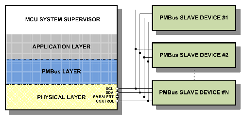
The general block diagram of a microcontroller-based distributed power management system interconnected by PMBus is shown in Figure 1. The control line shown controls multiple devices but in some applications multiple control lines are used to provide individual control. The MCU system supervisor can be a general-purpose microcontroller connecting to PMBus compatible slaves such as power supplies, buck/boost converters and PWM controllers. The hardware and software resources needed to setup an example application are explained in the following section.

Fig. 1. Components of a digital power management system interconnected by PMBus.
The example reference design uses the Texas Instruments MSP430F2132 MCU for implementing a PMBus host controller. This 16-bit ultra-low power MCU costs under $3 and is available with an integrated I2C peripheral, a programmable timer and interruptible I/O pins – key hardware features for a PMBus host. Hardware I2C peripherals used in PMBus host implementations typically run up to 100 kHz (standard I2C mode) and are capable of interrupt driven data transmission and reception. The current PMBus specification allows upto 400 kHz operation similar to fast I2C mode. The ability to issue an I2C ‘Re-Start’ condition between the command and data bytes of the transaction is also required. In the example design, the Universal Serial Communication Interface (USCI) module in the referenced microcontroller was used in I2C mode. A general purpose timer is required to detect inactivity on the bus as well as the clock low timeout. In the example design, the 16-bit Timer_A module in the referenced microcontroller was used. Two general purpose I/O lines are used to implement the SMBAlert and Control functionality. Similar to the I2C data and clock lines, the SMBAlert line is pulled high to the bus voltage when the bus is idle and pulled low by the slave to indicate an alert condition. This transition can be used to create interrupts allowing the host to handle faults promptly. The Control line allows the slave device to be turned ON or OFF in combination with commands on the bus. It can be configured as active high or active low, as required by the user.
Software resources
The software resources needed to implement a PMBus master application include a dedicated code space of 1-2 Kbytes on an efficient 16-bit MCU architecture. The software flow can be abstracted into user or application layer, PMBus layer and a physical I2C layer (see Figure 1). The application layer is responsible for accepting user commands and passing them to the PMBus layer. A list of user commands and the corresponding command codes can be defined and stored in a look-up table. The PMBus layer identifies the command codes corresponding to the user commands and also takes care of functionality such as calculating PEC bytes, handling timeouts and alerts from the slave. The PEC bytes are appended to the end of any transaction and are the result of CRC on all the bytes in the transaction, including the address bytes.
Handling timeout conditions can be easily accomplished using a programmable timer. The timer is set to a fixed timeout interval of 35ms (as specified in [2]) and works in tandem with I2C ‘Start’ and ‘Stop’ events on the bus. Most transactions on the bus will fit well within the timeout interval so it is sufficient to enable the timer at the start of the transaction and disable it at the end. If a timeout condition occurs, the host controller can be setup to reset the I2C peripheral and attempt a re-transmission if required. The Alert functionality is handled by setting up interrupts on a ‘high’ to ‘low’ transition on the SMBAlert line. Once the SMBAlert condition is detected, the host issues an Alert Response Address on the bus, the alerting slave then will place its device address on the bus. This allows the host to identify which of the multiple slaves on a bus issued the alert. The host can then read the identified slave’s status registers and makes a decision on how to handle the fault. The PMBus layer therefore acts as an intermediary, preparing the data bytes to be transmitted and processing information retrieved from the slave. The physical I2C layer mainly comprises of the interrupt service handler and serves to move data to and from the PMBus layer. The software stack is thus implemented as three abstracted layers with the PMBus and physical layers accepting commands from and passing data to the application layer.
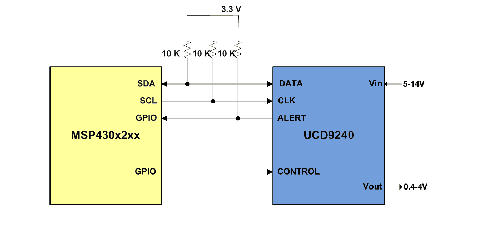
As an example application, a host microcontroller such as the MSP430F2132 MCU is interfaced to the slave UCD9240 synchronous buck controller (see Figure 2). The UCD9240 is a part of the UCD9k family of digital power controllers. This buck controller has a hardware PMBus interface that supports Version 1.1 of the protocol. Hardware PMBus slaves typically have an interface that can map PMBus command codes to memory locations and process received commands after validating the transaction by checking PEC bytes. The UCD9240 applications have features such as 1) 5-14V input range, 0.4 -4V programmable output voltage 2) PEC support and 3) Graphical User Interface (GUI) used to configure the control registers. Figure 2 shows the electrical connections between the host controller and the slave buck boost converter device. The alert, data and clock lines are pulled high to the bus voltage using a 10K ohm pull-up resistor. The actual pull-up value should be determined by the number of devices on the bus and the bus capacitance. The UCD9240 supports 5 mA pull-down for the PMBus communication lines. The control line can simply be tied to the control input of the slave and programmed to be active high or low. The implementation is straightforward and requires only the basic serial communication lines (clock and data) with two additional I/O pins.

Fig. 2. Connecting an MCU host controller to a PMBus slave using a 4-wire interface.
PMBus presents an efficient and easy-to-implement communication standard that eliminates the effort needed by host controllers to support multiple protocols. It is also highly compatible with systems having SMBus or I2C slave devices on the bus. One of the key strengths of this protocol is its diverse command language with specification-defined commands and support for additional user-defined commands. The protocol also addresses reliability requirements with features such as error detection and fault handling capabilities. The resources used in terms of software and hardware are a fair exchange for a power systems communication protocol that can be ported across any microcontroller. The protocol continues to gain popularity with increasing numbers of PMBus compliant hardware power management slave devices being released. The power management industry is seeing a shift towards digital supervisory systems and utilizing the PMBus protocol gives an edge in implementing an intelligent, optimized and flexible power control system while enabling seamless integration with existing analog technology. ■
Advertisement
Learn more about Texas Instruments


