Choosing which type to use depends strictly on its application
BY DAVID KENNY and ROBERT HENRY
Pletronics, Lynnwood, WA
http://www.pletronics.com
From simple RC oscillators, accurate to about 30,000 ppm, to atomic clocks with accuracies of greater than 0.001 ppb, there are clocking options to meet the needs of every application. For years, bulk acoustic wave (BAW) crystal oscillators satisfied the majority of requirements, providing accuracies in the 10-ppm range. Less-accurate options, such as SAW oscillators, ceramic resonators, and IC oscillators, each have advantages to meet specific needs.
Quartz-based devices have long been a standard by which most other timing devices have been compared. The history of quartz as a stable, controllable, high-quality material for frequency selective and clocking devices is universally recognized, and frequency vs. temperature response, aging, and jitter and phase noise characteristics are well chronicled in the industry.
The relatively recent introduction of MEMS-based oscillators has been accompanied by claims that this technology would finally replace quartz by providing lower costs, shorter design and production cycle times, excellent shock and vibration performance, and superior signal quality. Despite these claims, few studies have been available to help understand the performance characteristics of MEMS oscillators. This investigation seeks to provide a direct comparison of MEMS oscillators with traditional quartz-resonator-based oscillators.For years, bulk acoustic wave (BAW) crystal oscillators satisfied the majority of requirements, providing accuracies in the 10-ppm range.
Study methodology
The results presented here are based on application of established typical frequency-control industry measurement techniques and represent technology that was commercially available at the time of this study in 2008. A number of electrical characteristics were reviewed, including frequency vs. temperature; phase noise – jitter; short-term stability; startup time; current; and long-term stability (aging).
Due to space limitations here, only some of the data regarding phase noise/jitter and short-term stability are presented. A .pdf copy of the complete study is available at www.pletronics.com/ple/pages/documentation/.
Products chosen for comparison were all available from national distribution. All had CMOS-level output, 3.0- or 3.3 V operation, and the output frequencies of 25 and 50 MHz. The BAW quartz crystal oscillators tested were fundamental mode for the 25-MHz parts and third overtone at 50 MHz. The results presented here are either that of a typical device or the average of several devices of that part number.
Phase noise/jitter
The Agilent 5052 signal source analyzer test system was used to perform the measurements. This system measures the level of the output signal that is other than the desired output and is referenced to the level of the actual main output. The oscillators were operated in the same well capacitor bypassed fixture with a 15 pF load powered by a low-noise Agilent linear power supply.

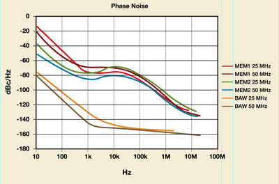
Fig. 1. The phase noise plots reveal much about the design and characteristics of these different technology devices.
The higher levels of phase noise (see Fig. 1 ) demonstrate that MEMS oscillators are not an equivalent technology. Current communications and data transmission applications will very likely have problems with jitter at the levels indicated in the Agilent test system.
The phase noise plots reveal much about the design and characteristics of these different technology devices. The in-close phase noise level (
The 1 to 100 kHz reveals information about the design. The MEMS oscillators use a phase-locked loop (PLL) design with a MEMS resonator being phase locked to a VCO in an M/N synthesizer loop. The phase noise level of the MEMS oscillators is the result of the combined effects of the PLL loop bandwidth, selectivity of the VCO, and Q of the primary resonator. The quartz resonator device is operating at the output frequency and does not have the added noise signals of the PLL in the output.

Phase noise can be integrated over a defined frequency region and converted from the frequency to the time domain in order to provide an rms Jitter value (see Table 1 ). This is a common practice for the computation of jitter for quartz crystal based resonators, which normally have jitter performance that is equal or exceeds the best oscilloscopes.
Short-term stability
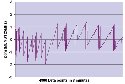
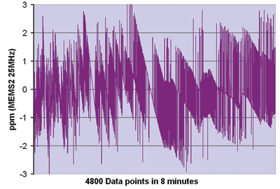
The short-term stability data shown here (see Fig. 2 ) was determined as frequency measurements taken every 0.1 s for 8 min with the oscillator stabilized at 25°C within a few tenths. The parts were all tested with an Agilent 53152 frequency counter operating with a rubidium atomic frequency standard reference. The frequency change is shown in parts per million referenced to the first reading.

Fig. 2. MEMS1 resonator oscillator (a), MEMS2 resonator oscillator (b). The data demonstrate that the two technologies are not equivalent and also reveal much about the design and characteristics of the different devices.
The charts for BAW oscillators (not shown here but available in the complete study) are familiar to most. Typical of BAW oscillators was less than ±0.02-ppm variation for the same test, which resulted in a straight line that is on the 0 deviation graph line.

Fig. 3. BAW oscillators offer less than ±0.02-ppm variation for the same test, which resulted in a straight line that is on the 0 deviation graph line.
The data demonstrate that the two technologies are not equivalent and also reveal much about the design and characteristics of the different devices:
• The lower Q in the MEMS devices result in more frequency variations.
• The MEMS devices show step changes of a few parts per million. This is characteristic of a temperature compensation circuit correcting for the resonator’s temperature changes. This would be a form of digital changing in the PLL circuit to correct the frequency.
• The MEMS1 and MEMS2 designs (two different manufacturers) are quite different in how often the digital compensation switches.
• The BAW crystal resonator is much quieter, the result of much higher resonator Q and has no digital correcting signals.

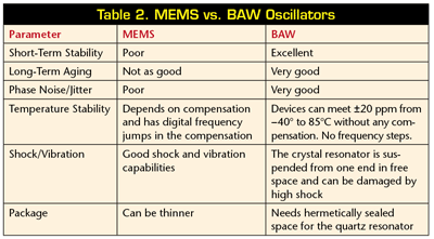
The study discussed here in part and summarized in Table 2 compared a number of different electrical characteristics of commercially available BAW and MEMS oscillators using established measurement techniques. The results indicate that the two technologies are not interchangeable. Frequency variations, from both lower Q and digital temperature compensation in the MEMS oscillators resulted in frequency fluctuations that are unacceptable in many applications.
Past attempts at digitally temperature compensated BAW oscillators failed in the marketplace due to the compensation steps, despite the fact that the steps were significantly smaller than those used in MEMS oscillators. For example, today’s cell phone temperature-compensated crystal oscillators (TCXOs) are all analog compensated.
MEMS oscillators appear well suited to high-vibration environments, to non-critically-timed applications, and to applications where the signal-to-noise ratios are not critical. Applications that have complex modulation schemes, very-high-speed communication, or that require excellent signal-to-noise performance (for example, A/D converters) will continue to be clocked by BAW devices, taking advantage of the exceptionally high Q and excellent temperature stability of quartz. ■
Advertisement
Learn more about Pletronics


