Driving higher levels of efficiency in motor design
Modern motor and motor drive solutions reduce wasted energy, increase reliability, and lower component count
BY ERIC ZHANG
Fairchild Semiconductor
South Portland, ME
http://www.fairchildsemi.com
High energy costs and government power consumption regulations are making motor efficiency a global concern. In response, industry has developed a number of motor and motor drive solutions to make it easier for designers to reduce wasted energy, increase reliability, lower component count and contribute to a greener world.
In particular, demand has been strong recently for energy-saving household appliances. It’s easy to see why: a refrigerator accounts for more than 10% of a home’s electricity consumption. Because a refrigerator’s compressor motor is primarily driven in low speed, there is tremendous potential for energy conservation, which can be made possible by simply improving the motor-driving efficiency in low-speed drives.
Similarly, with an estimated 65% of industrial electrical energy used by electric motors, it is no wonder that major players in the industry are increasingly seeing energy reduction as a key to improving their profitability and competitiveness. Reducing energy consumption from electric motors can be accomplished in two main ways: making the motors themselves more efficient and using variable-speed drives to efficiently control the operating speed. We’ll examine both methods.
Variable-frequency drives
While induction motors have been used in appliance design for nearly 100 years, newer appliances now use more efficient, compact, and lighter motors; these can effectively be divided into the brushless dc motor family and the switched-reluctance motor family. Both the brushless dc and the switched-reluctance motors use a microcontroller or DSP to synthesize waveforms that are then amplified using power switches such as power MOSFETs or IGBTs.
The rising cost of energy is driving renewed interest in brushless dc motors with variable-frequency drives. These efficient and versatile motors have high torque-to-weight ratios, but the main factor preventing their widespread adoption in appliances has been cost and the overall complexity of the drive design.
Switched-reluctance motors have been popular in appliances such as vacuum cleaners and hand tools where motor noise and torque ripple are less of a concern. Switched-reluctance motors feature high-torque and high-speed operation at a very competitive price point. Both the brushless dc and the switched-reluctance motors use a microcontroller or DSP to synthesize waveforms that are then amplified using power switches such as power MOSFETs or IGBTs.
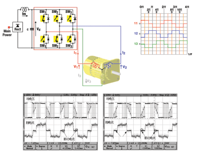
Variable-frequency drives can be designed in several different ways. The most popular low-frequency drive scheme for a typical three-phase motor is a trapezoidal waveform drive (see Fig. 1 ).

Fig. 1. Trapezoidal waveform control method and real test waveform.
If higher efficiency and performance are needed, a PWM approach is used to produce a sinusoidal waveform. For further efficiency improvements, a space vector modulation scheme can be used.
Three-phase synchronous motors with permanent magnets come in two popular variants: the sinusoidal PM synchronous motor and the trapezoidal BLDC motor. While similar in many ways — both are electronically commuted — there are two main differences:
• Motor construction . The shape of the BEMF inducted-voltage sinusoidal (PM synchronous) motor vs. the trapezoidal (BLDC) motor.• Control . The shape of the control voltage: three-phase sinusoidal (all three phases connected at one time) versus rectangular six-step commutation (one phase is non-conducting at any time).
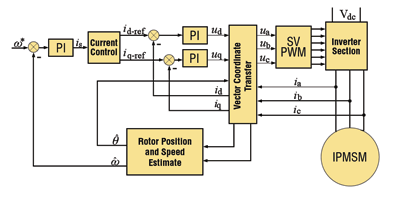
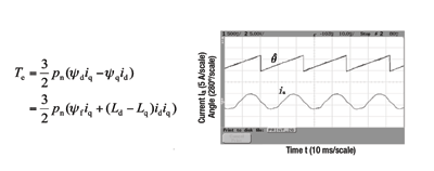
Sinusoidal PM synchronous motors are increasingly popular for new drives, replacing brushed dc, universal, and other motors in a wide variety of applications. The main reasons are that it provides better reliability without brushes as well as better efficiency, lower acoustic noise, and other benefits (see Figs. 2 and 3) .

Fig. 2. Interior permanent magnet synchronous motor (IPMSM) vector control system block diagram.

Fig. 3. Torque equation and phase current and estimate angle waveform.
Smart power modules
Along with smaller motors that are easier to design, smart power modules (SPMs) provide the power interface to the microcontroller or DSP. The primary advantages of these modules over discrete solutions are decreased parasitic inductances and higher reliability. This is due to the use of “sister” dies for all the switches within the modules, so they have similar electrical characteristics, as well as for the ease of testability.
These SPMs are a drive circuit that can be interfaced directly to a low-voltage TTL or CMOS outputs of the microcontroller as well as additional protection circuitry. The modules implement a thermistor to monitor junction temperatures, logic to prevent accidental turn-on of both high-side and low-side switches, dead-time control, and the appropriate drive wave-shaping circuitry to minimize EMI. The driver ICs in these modules can be optimized to switch the power devices with minimal EMI and drive losses.
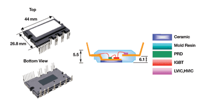
Smart power modules are designed to maximize design flexibility, allowing it to be used for a wide variety of input voltage and power ranges. Figure 4 contains a picture and an internal structure illustration of the Motion-Smart Power Module (SPM) in Mini-DIP packaging. This Motion-SPM is a compact power module that integrates power components, high- and low-side gate drivers, and protection circuitry for ac 100 to 220-V low-power motor drive inverter control into a dual–in-line transfer mold package.

Fig. 4. SPM 3 profile and internal structure illustration. High-voltage bridge driver
A trend enabling compact, low-cost modules to revolutionize motor drives has been the emergence of high-voltage (600-V) bridge drivers. These drivers are the result of careful design to reduce parasitic drain source capacitance internal to the high-voltage IC process, resulting in drivers rugged enough to withstand negative voltages over –9 V.
Positive and negative spikes on the power supply voltage don’t cause the driver to latch and lose gate control, a big change from the gate drivers of the last decade. Matched propagation delays below 50 ns enable switching up to 100 or 150 kHz.
The addition to common-mode dV/dt noise cancellation circuitry within the IC helps to reduce the possibility of false turn-on, which also has helped in making the power circuitry more rugged as well as more compact by eliminating additional filter components. The lower quiescent currents of the modern ICs such as the FAN7382 and the FAN7384, decrease operating temperature and thereby increase reliability.
Another big advantage is the reduction in board space and cost that comes from replacing the four isolated power supplies and opto-isolation circuitry between the microcontroller pc board and the power switch pc board that were very common in motor drives of a previous generation.
IGBTs: NPT vs. PT
For about two decades, the power- switching device of choice for motor drives has been the IGBT, which can be designed to minimize losses at a certain switching frequency. For the motor drive industry, this has meant that there are IGBT families each targeted to switch at about 5 kHz for some consumer motors; about 20 kHz in many industrial motor applications; and even higher frequencies for applications other than motors.
Improvements in IGBTs such as conduction voltage and turn-off energy per switching cycle have also contributed to reliable, low-cost modules. The last five years has seen vast improvements in the capabilities of the conventional IGBT and the popularization of the new non-punch-through (NPT) IGBTs. The NPT IGBT, while it looks similar to a conventional or punch-through IGBT, is manufactured in a very different way. Unlike the MOSFET or the conventional IGBT, the NPT IGBT uses P region and Back Metal regions implemented during wafer processing.
NPT IGBTs are generally not as fast or as low in conduction voltage (VCE(sat) ) as their conventional counterparts. However, they are usually more rugged. The ability to withstand significantly longer periods in short-circuit or overcurrent conditions makes them popular in motor control applications. Furthermore, if we examine the switching waveforms of the two types of IGBTs, it can be seen that the EMI generated by the NPT IGBT is significantly less than the punch-through IGBT.
The NPT IGBT has a fall time that basically has a single slope.
On the other hand, the fall times of the conventional IGBT consists of a region where the dI/dt is very rapid, but following this is a long tail where the rate of fall of current is very low and the device losses are high. In the high-dI/dt region, the EMI generated by the conventional IGBT is high and generally has the potential to affect the drive circuitry, often making it necessary to isolate the drive circuit from the power switches. Another advantage of the NPT IGBT is that it can be made to have a positive temperature coefficient to VCE(sat) — a valuable feature that is valuable when paralleling IGBTs.
Fairchild Semiconductor’s series of low–on-resistance 600-V SuperFET MOSFETs specifically address the DPAK (TO-252) ultra-slim, low-profile device requirements for motion applications. To minimize switching and conduction losses and meet system efficiency requirements of some high-switching frequency motor control designs, these products offer as little as one-third of the on-resistance (0.6 to 1.2 Ω) of traditional planar MOSFETs. They also can withstand both high-speed voltage (dv/dt) and current (di/dt)-switching transients necessary for motor system to operate reliably at high frequencies. ■
For more on motors, visit http://www2.electronicproducts.com/Components.aspx.
Advertisement
Learn more about Fairchild Semiconductor


