Improving measurement of optical device performance
Fast polarization switching makes it possible to measure insertion loss and polarization-dependent loss in one fell sweep
BY MICHAEL KELLY
Agilent Technologies, Santa Clara, CA
http://www.agilent.com
Primary performance data for passive fiber-optic devices is provided by spectral measurement of optical insertion loss (IL) and polarization-dependent loss (PDL). Often used to characterize optical couplers and splitters, the measurements are especially useful for wavelength multiplexers, switches, and add/drop filters for static as well as reconfigurable fiber-optic networks.
A new implementation of the industry-standard swept-wavelength Mueller Matrix method — an implementation based on fast polarization-state switching and synchronized logging of both signal power and state of polarization — allows complete IL and PDL measurements during a single continuous wavelength sweep. This improves measurement throughput and quality by reducing sensitivity to environmental disturbance (such as vibration and drift) resulting in excellent measurement reproducibility and accuracy as well as ease of setup.
Answering today’s challenges
Today’s reconfigurable fiber-optic networks use components like wavelength-selective switches or dynamic gain equalizers that require multiple measurements for different device settings. The measurements are used for calibrating operation as well as verifying performance.
IL indicates first the impact of the device on the network’s optical power budget. The IL’s wavelength dependence quantifies the device’s usefulness over the desired wavelength range and, in the case of devices like filters and multiplexers, establishes the actual functionality of the device for combining and separating optical channels. In this case, low in-channel IL and high out-of-channel IL are required, often determined with high wavelength resolution.
Since the polarization of light passing through standard optical fiber typically changes frequently (due to temperature variations and mechanical strain and movement), any dependence of a device’s insertion loss on polarization results in unpredictable variations of signal power with time. Thus most components should have low PDL.
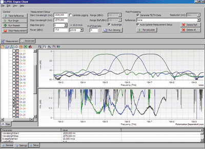
Consider the case of measurements for 40-channel array waveguides (AWGs), which are used to combine signals from multiple transmitters at different wavelengths onto a single fiber at the source end of a fiber, and then to separate the wavelengths to multiple receivers at the other end. Figure 1 shows the IL and PDL for three selected channels from a 40-channel AWG.

Fig. 1. An IL and PDL display of three channels from a 40-channel AWG measurement.
The IL traces show about 60 dB dynamic range and permit the position and width of the channels to be determined, as well as the isolation provided from other wavelength channels. The graph displays IL versus either wavelength or the equivalent optical frequency, and shows that the channels are centered on the ITU-T 100-GHz grid.
The PDL traces allow determination of the PDL within each channel, and in particular the maximum value within each operating wavelength range. Out of the passband, the PDL measurement can become noisy in the regions where the signal is extremely weak.
The Mueller Matrix method
The measurement of PDL with the Mueller Matrix method involves determining the IL of the component at a set of at least four input states of polarization (SOP) with known orientation to another. The insertion loss itself is the ratio of output optical power to input power, usually expressed in dB.
The input power is usually established with a reference power measurement of the source before connecting it to the component input fiber. From the set of IL values, the Mueller Matrix calculation determines the maximum and minimum transmission for any input SOP, from which their ratio gives the PDL, also expressed in decibels. This method has been adopted in international standard IEC 61300-3-2.
The power of the Mueller Matrix method (versus simply measuring output power while the polarization is scanned over a sufficient sampling of all possible SOP) becomes apparent when it is necessary to measure the wavelength spectra of IL and PDL together. For instance, components for dense-wavelength-division-multiplexing (DWDM) networks, which use multiple channels typically separated by 50 or 100 GHz (0.4- or 0.8-nm spacing in the 1,550-nm wavelength region), are commonly measured with a wavelength resolution of 10 pm or less over a range of 50 nm or more. Measuring spectra with so many points would be prohibitively long using the all-states polarization scanning method.
Instead, the Mueller Matrix method lets users measure IL and PDL spectra by continuously sweeping the wavelength of a tunable laser and synchronously sampling the output power with a power meter. This can be performed over four such sweeps, each with a different input state of polarization. Using fast sweep rates like 80 nm/s, the IL and PDL spectra can be quickly obtained.
If the device has multiple output ports, each port can be simultaneously measured with a separate power meter. This method has been standardized for DWDM components in IEC 61300-3-29.
The Mueller Matrix data can also find the IL spectra at selected SOPs such as those where the optical electromagnetic field is oriented with a planar component, corresponding to transverse electric or magnetic (TE or TM) modes, without needing to adjust for a measurement with the signal exactly in that orientation.
However, even with such sweep rates, several seconds typically pass between the measurements of each SOP set at any particular wavelength. Unfortunately, the SOP of a signal passing through optical fiber, even those used to connect the component and the instruments, is sensitive to temperature drift, mechanical movement, pressure and vibration.
If such effects change the input SOP to the component between samples in the SOP set, the accuracy of the Mueller Matrix calculation is degraded. Anything that causes a change in optical power among the wavelength sweeps also disturbs the measurement.
Addressing these concerns generally requires special care in fiber placement and fixing as well as maintaining workplace stability, and encourages the use of additional real-time power monitoring of the signal input to the component. In addition, the instrumentation used to control the SOP generally depends on wavelength that needs to be corrected by the software for highest accuracy.
Fast-switching PDL method
The concerns just mentioned can now be largely alleviated by implementing Mueller Matrix measurements with a fast SOP-switching polarization synthesizer. This instrument uses solid-state electro-optic switching, like that used in optical modulators, to switch the signal through the selected set of SOP during a single continuous wavelength sweep of the tunable laser.
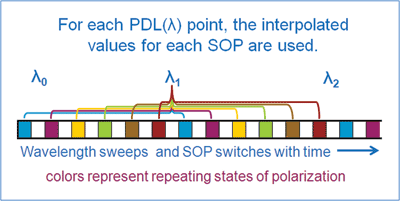
The samples are taken with small-wavelength spacing, so that by using interpolation an accurate determination of the IL at each SOP for a point on the spectrum is quickly obtained. In a standard configuration, the SOP set is scanned in less than 0.5 ms, so the measurement results are very robust against normal fiber movement and temperature drift. An illustration of this simultaneous wavelength sweep and polarization switching is shown in Fig. 2 .

Fig. 2. Visualization of the polarization switching during a wavelength sweep. For each PDL (λ) point, the interpolated values for each SOP are used. Colors represent repeating states of polarization.
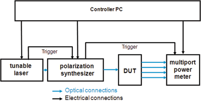
For each sample the SOP is switched and when the new SOP is reached, the synthesizer electrically triggers the power measurement by the power meters. At the same time it also measures and logs the SOP and power of the output signal to the component, providing correction for any changes since the reference power measurement and any dependence of the output SOP on wavelength.

Fig. 3. Simplified diagram of the hardware configuration for single-sweep IL and PDL measurements.
The wavelength itself is measured and logged by the tunable laser, synchronized with electrical triggers to the other instruments (see Fig. 3 ). Finally the controller PC collects the power data from the power meters, the wavelength data from the laser, and the SOP data from the synthesizer. With respect to the previously measured reference data, the PC calculates the IL and PDL traces using the Mueller Matrix method. Depending mainly on the number of points needed in the spectra, this measurements can be taken in under 10 s. ■
Advertisement
Learn more about Agilent Technologies


