Heterodyne vs. direct conversion architecture
The understanding of both architectures is a must in order to design the right solution for 4G base transceiver stations
BY CHUCK SANNA
Texas Instruments, Dallas, TX
http://www.ti.com
With 4G wireless standards such as WiMAX and LTE poised for deployment, many cellular network operators are looking for more efficient use of wireless spectrum and cellular base transceiver station (BTS) sites to support cost-effective network rollouts. With these needs, demand is increasing for remote radio heads to support multiantenna transceiver architectures such as diversity, MIMO, and smart antennas.
In many cases, as many as four receive and four transmit channels (4×4) in one radio are required. Such multiantenna receivers provide the ability to offer wide cellular coverage areas in diverse environments, while still maintaining necessary performance levels to receive and transmit the large bandwidths required for 4G and multicarrier 2G and 3G standards. But because each channel requires its own RF-to-DSP signal chain, building a size-, power-, and cost-efficient radio head to support a 4×4 system can be a great challenge.
Much of the base station’s cost is relatively defined by the type of wireless system being targeted. Each radio head antenna needs its own receiver low-noise amplifier (LNA). Each power amplifier (PA) requires a driver amplifier (DA) and potentially a digital predistortion (DPD) solution.
Digital baseband processor needs depend heavily on the standard, bandwidth, and receiver count. However, the architecture by which the received RF signal is converted to digital baseband is not as constrained.
The newest generation of A/D converters (ADCs) can sample intermediate frequencies (IF) at baseband (loosely dc to 20 MHz), low IF (20 to 100 MHz) and high IF (100 MHz and greater). Because of this flexibility, the receiver portion of a 4G, 4×4 base station can be configured along two main architectural paths: an IF sampling receiver with heterodyne mixing stages down-converting the carrier frequency to the IF sampled by the ADC; and a direct down-conversion receiver in which the carrier frequency is converted through quadrature demodulation into two baseband signals for digital conversion.

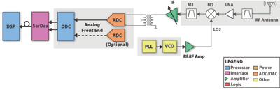
Fig. 1. The heterodyne receive architecture uses an ADC to sample the full signal bandwidth of interest.
Heterodyne solution
The heterodyne (IF sampling) receive architecture (see Fig. 1 ) uses an ADC to sample the full signal bandwidth of interest. A series of passive and active components including transformers, mixers, amplifiers, attenuators, and active, passive, and SAW filters is needed to down-convert the carrier RF to either a low or high IF for sampling while maintaining signal integrity.
Because each of the main blocks comprises discrete or lightly integrated components, the heterodyne architecture is very flexible and allows for a basic design to be easily modified for accommodating different wireless standards and carrier frequencies. But due to the large number of discrete components required, heterodyne systems use large amounts of board area and can become cost challenging when not using commonly available components. These drawbacks are multiplied when designing multiple antennae systems.
In the heterodyne architecture much of the analog performance burden rests on the ADC and gain block driving it, typically an active filter or transformer with a passive anti-aliasing filter. For wideband signals like those found in WiMAX and LTE, the SNR and SFDR (or IMD) set the system noise and dynamic range levels.
Additionally, the ADC must operate with a sampling frequency more than twice that of the sampling bandwidth so that the antialiasing filter skirts can drop from passband to stopband without crossing into adjacent Nyquist zones. A typical 20-MHz system uses a minimum ADC sampling rate of 76.8 Msamples/s. Many systems, though, use a sampling rate of 92.16 or 122.88 Msamples/s to give the filter skirts more room, but this adds cost as ADC prices increase with guaranteed sampling speed.
Another major factor in changing the cost/size/power balance in a heterodyne system is your choice of sampling IF. Lower IFs such as those centered in the middle of the first or second Nyquist zone, 30.72 and 92.16 MHz, respectively, for a 122.88-MHz sampling rate, can require an additional IF stage between the RF and sampling IF, adding the cost and size of an additional mixing stage.
IFs centered in the third (153.6-MHz) or fourth (215.04-MHz) Nyquist zones do not require the additional mixing stage. However, because the SNR and SFDR performance of ADCs degrades with increased IFs, higher IFs can increase cost as higher-resolution, higher-performance ADCs must be used.

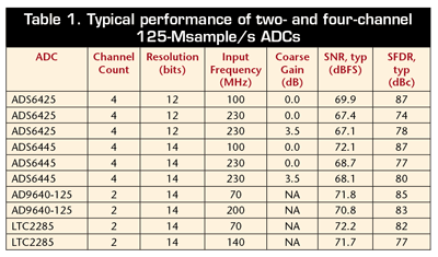
For example, Table 1 shows the typical performance of a four-channel 125-Msample/s ADC such as the ADS6425 from Texas Instruments, which is suitable for sampling each antenna of a 4×4 system at 122.8 Msamples/s. At 100-MHz IF, it has typical 69.9-dB SNR and 87-dB SFDR performance, translating to 11.3 effective bits of resolution (ENOB). At 230 MHz, the performance drops to 67.4-dB SNR and 74-dB SFDR, reducing ENOB to 10.75. In order to increase SFDR back to 80 dB at this IF, a 14-bit version of this ADC is needed, such as the ADS6445.
Using the programmability functions of this ADC family SFDR can be improved while maintaining 68.1-dB SNR and 11 ENOB. But this induces a direct cost increase as 14-bit ADCs are more costly than 12-bit ones. In this case, approximately 66% more. However, some of this cost increase can be mitigated as the higher IF can improve filter performance, allowing the use of lower-sampling-speed, lower-cost ADCs.

Fig. 2. In the direct down-conversion receiver rather than using a single ADC to sample an IF, the carrier frequency is directly converted to two baseband signals, I and Q, which are then sampled by ADCs.
Direct down-conversion solution
In the direct down-conversion receiver (see Fig. 2 ), rather than using a single ADC to sample an IF, the carrier frequency is directly converted to two base band signals, I and Q, which are then sampled by ADCs. Although this type of architecture requires twice the number of ADCs than the direct approach, eight in total for a 4×4 system, much lower sampling rate ADCs can be used because the bandwidth of interest per ADC is halved.
Additionally, with the signals now located at baseband, lower power ADCs designed for limited IF performance can be used. In the article “A scalable, efficient multichannel diversity receiver [1],” Philip Pratt analyzes such a receiver for a 4×4, two-channel diversity system targeted for 3G applications using an ADC principally designed for portable medical imaging. Compared to a four-channel 125 Msample/s ADC, octal ADCs discussed in the article reduce the total power consumption of the ADCs by over 50% while maintaining a similar cost.
While the performance burden is reduced on the ADC section, it is transferred to the RF section in the demodulator block and the local oscillator (LO) feeding it. Any phase or gain mismatches between the I and Q signal chains will create in-band images that reduce the receiver’s overall SNR and error vector magnitude (EVM), increasing system’s bit error rate (BER).
For single-carrier 3G receivers, single-chip quadrature demodulator/filter/ADC buffer devices combine with high-performance PLL/VCOs for the LO feed to minimize these effects. But for multicarrier 4G signals, such highly integrated single-chip demodulator solutions are not yet available, requiring solutions comprising discrete components. With a total of eight down-converted channels, the increase in total power consumption, board space and cost can be quite significant, potentially higher in some or all respects in comparison to the heterodyne approach. ■
References
[1] “A scalable, efficient multichannel diversity receiver,” by Philip Pratt, Electronic Products , 04/03/08: http://www2.electronicproducts.com/A_scalable_efficient_multichannel_diversity_receiver-article-facntexas-apr2008_Print-html.aspx
Advertisement
Learn more about Texas Instruments


