LEDs provide higher efficiency than incandescent designs, but they also have different electrical requirements
BY PAUL YEAMAN
Vicor, Andover, MA
http://www.vicorpower.com
Recent breakthroughs in LED technology have enabled LEDs with a broad spectrum of light output to be produced and not just the traditional red and green derivatives. Hence the sheer numbers of LEDs used in products (lighting and otherwise) is growing exponentially.
LEDs are finding their way into new applications from flashlights, to vehicle headlights, to LCD TV display backlights. Overall, the primary driver behind this growth is the increase in efficiency (more lumens of light created for each watt of energy expended) of LED technology.
Electrical requirements
LEDs have different electrical requirements than their incandescent predecessors. In addition, the optimal power solution for driving LEDs varies based on the power level and overall system requirements.
In traditional lighting solutions (such as incandescent lighting), the load looks resistive. The power consumption and thereby the intensity of the light is a function of the voltage applied to the light and the resistance of the light (per Ohm’s law).
The intensity increases or decreases based on the input voltage. As an example, consider the headlights of a vehicle when the engine is started. While the engine is cranking, the voltage from the battery is low, and thus the headlights are dimmed. Once the engine turns over, the battery voltage recovers and the headlights regain their normal intensity.
LEDs behave fundamentally differently from traditional incandescents. LED intensity is controlled by modulating the LED current and the resistance of an LED load varies with applied load. Rather than using a constant voltage and resistance to maintain a constant lighting intensity, an LED needs a constant current. How this is achieved varies based on an LED’s power level.
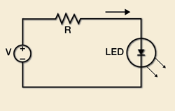
For a very-low-power LED, a very simple circuit such as shown in Fig. 1 is almost always sufficient. The effective resistance of the LED is very small compared to R, so the current flowing through the LED is determined by V/R. The drawbacks are as follows:
Intensity is a function of voltage. A variation in V essentially changes the current, hence the LED intensity. Returning to the original example of a vehicle headlight – the light would still dim while the engine was cranking.The solution does not take advantage of LED efficiency benefits. Since R is very large with respect to the LED resistance, the majority of the power is lost in R.

Fig. 1. Simple resistive-limited LED power solution.
High-power LEDs
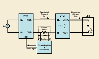
For higher-power LEDs, a solution with controlled current is needed to maximize the efficiency advantage of an LED. One example of such a solution is shown in Fig. 2 .

Fig. 2. Controlled current solution for powering LEDs.
The V•I Chip PRM regulator and VTM voltage transformer are designed to provide a regulated voltage. In order to use the PRM and VTM to power an LED, it is therefore necessary to modify the operation of the PRM to provide a regulated current. This is accomplished by the implementation of a current amplifier and compensator.
Using the PRM and VTM to provide a constant current provides several advantages over conventional approaches. The implementation of a VTM in a system provides point-of-load current multiplication. The output current of a VTM is proportional to its input current by a fixed turns ratio, K, per the equation below:
IOUT = IIN /K
Thus, in a controlled-current application, the input current to the VTM can be sensed and regulated to control the output current. Sensing a lower current requires a smaller sensor, which dissipates less power and improves overall efficiency. Also the high efficiency and high power density make the overall LED system small and cool and maximize the output in lumens per watt dissipated.
One important additional benefit is that the current through the LED (IOUT in the equation above) is not a function of the input voltage. Thus in our example of the vehicle headlight, the LED’s intensity would remain constant as long as the current through the LED remained constant, regardless of the battery voltage. This is possible because the PRM is a variable negative resistance that can change with V, thus allowing a means of keeping the current constant.
Even more important, the resistance of the PRM is effective, not real, meaning that the power lost is minimal and not a function of the value of the effective resistance. Thus the majority of the power is lost in the LED, making the solution as efficient and effective as the LED used.
Some drawbacks to this solution include the complexity this is obviously more complex than the solution shown in Fig. 1, and thus requires more care and control to implement properly. With increasing complexity comes higher cost as well making this a better solution for higher-power LEDs where the savings in power (and energy cost of operating the LED) more readily offsets the increased cost and complexity.
Finally, with the varying power requirements of LEDs, different solutions are available ranging from simple to complex. Resistive current limiters (Fig. 1) are simple and cost effective, but inefficient and ill-suited for higher power LEDs.
Adjustable current sources (Fig. 2) maximize efficiency and size, but have a higher cost and complexity associated with them. Adjustable current sources offer additional benefits such as immunity to input voltage fluctuations that may or may not be important in the overall system objectives. The designer of an LED power supply should be aware of the different solutions available for powering the LED as well as the objectives of the overall system. ■
Advertisement
Learn more about Vicor


