Scalable power for today’s content-oriented telecom
Power interconnections, like the pyramid busbar, help do away with fork-lift upgrades and allow modular, high-efficiency systems
BY LARRY LUTZ
Eltek Valere, Richardson, TX
http://www.eltekvalere.com
For many telecommunications carriers, the advent of broadband networking technology changed their networks and business model dramatically. From an infrastructure perspective, carriers shifted much of their investment away from the central office and to the outside plant to meet the demand for DSL connectivity.
But now the broadband era is shifting to a new phase, with carriers beginning to use their high-bandwidth network for video and Internet-based services like IPTV or “cloud computing.” This is putting the infrastructure focus back on the CO.
One of the impacts of this shift is that the CO power infrastructure is being rethought from the bottom up to be more scalable, higher efficiency, and more manageable.
Historically, CO power systems have been large, monolithic systems designed for an era when load was easy to predict. The CO had a 5ESS voice switch installed to meet the demands of a known number of lines. To power this system, a line of rectifier bays and distribution would be permanently installed.
Many of these power systems, installed in the 1970s and 1980s, are still in service, but they are hardwired, nonmodular systems that cannot be expanded with new higher power rectifiers. In some cases, the rectifier line can be extended but this is difficult. When a dramatically increased amount of power is needed, many times it means installing a brand new power system while the existing bays sit “retired in place” — turned off and left on the CO floor.
Many improvements have been made to power systems over the years. A change from ferroresonant rectifier technology to switching rectifiers has boosted power conversion efficiency from around 80% to 96%. Additionally, the systems have gone from fixed and monolithic to hot pluggable for upgradability with higher power density so they are lighter weight. On the management front, system controllers have added improved back-up battery control, system control, and networkability.
But one aspect has stayed the same — the busbar interconnect. Interleaved busbars are still the standard for CO power systems, and they dramatically limit the ability to expand these systems.
Needs of new CO
Today’s CO power systems must be engineered for a world where load is much harder to predict. The 5ESS switch has given way to modular voice switches and soft switches running on high-performance servers. IPTV and other services need their own servers, storage, and networks. With all of the technologies changing, the CO power planner has not just one moving target to consider when planning his implementation, but a bunch of them. Monolithic power systems don’t match this new need because they don’t easily address the more open-ended power demands of the facility.
Many carriers are coming around to a perspective that power, while not a revenue generator, is an increasingly significant part of the planning of a facility. The choice of a power system can impact direct operating expenses, but also soft costs like upgradability and manpower needed for maintenance and operations.
This thinking has led to a demand for a new busbar interconnect architecture for CO power. Power systems are composed of rectifier bays, back up power systems (typically a combination of batteries and diesel gen sets) and distribution bays. High power density allows power systems to scale to multiple 10s of thousands of amps in size, but realistically the back up battery plant and cable plant are the limiting factors. Beyond 10,000 A, the battery plant is so heavy that it stresses flooring. Distributing the power is problematic beyond 10,000 A as well, because it’s not practical to have that much load near the power system and the copper power buses need to traverse long distances, which is costly and inefficient.
Interleaved busbar
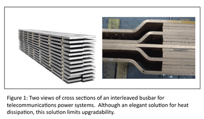
The defacto standard for interconnecting monolithic power systems since the 1990s has been the interleaved busbar. In common practice, most CO power system busbars are typically 6-in.-wide copper bars with a rating of 1,000 to 1,200 A of power capacity depending upon thickness (typically around a quarter inch thick). Interleaving involves connecting together multiple copper busses each with an airgap between them until you get the proper ampacity. For a 10,000-A bus, for example, the construction could include 10 busbars with nine air gaps.

Temperature rise is an important factor in expanding these power systems, and this is impacted by the size of the busbar, current load, heat from adjacent busbars, ambient temperature and other factors.
Technically, interleaving is an elegant solution to the temperature issue because the air gap provides airflow around the individual busbars. Where the busbars come together at a meter shunt, the multiple points of contact help to distribute the heat across the interconnect.
The busbar constructions are long because they typically extend from the power system into the ceiling and run overhead throughout a switching center, allowing each rack of equipment to tap into the power. Interleaved busbars must be built into the bays, setting the power capacity of these interconnects at the time of construction and making it difficult to easily expand the rated capacity to meet larger load levels.
Expanding a busbar system involves inserting new busbars into the air gaps to increase the capacity. This involves taking the power system offline and loosening the entire system for the all of the load, and then forcing the new bars into the air gaps.
Pyramid busbar alternative
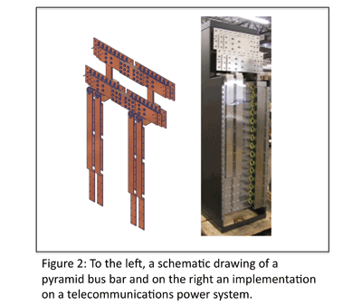
In contrast, the pyramid busbar system is an entirely different power plant bus architecture that uses cascading conducting plates to interconnect the busbars. In a typical implementation, four vertical busbars will connect the various power shelves — each set of two serving a different power bay. At the top they are interconnected using plates to tie them together. Each layer of the pyramid conducts up to 3,000 A, but the bays themselves can support up to 10,000 A, so three sets of plates are cascaded to support the power levels.

There is no room for airgaps in this design, so the entire bus structure must be slightly larger to carry the current, additionally the copper must be tin plated to absorb the heat transfer from the adjacent plate.
The advantage of this system is in its flexibility. Whereas lengthening, extending or expanding the capacity of the power system is limited by the interleaved solution, with the pyramid bus structure, it’s possible. New power systems can be located adjacent to the existing one, and the pyramid bus extended to include these new bays. The bus is modular in the sense that it is segmentable and existing power facilities don’t need to be taken down for new facilities to be added.
This makes power provisioning much more economic because it can be purchased only as needed and then upgrade as the facility has anticipated or unanticipated growth.
The pyramid architecture is exposed in the back and new busbar plates can be added to expand the capacity in a modular way. Right sized systems can be bought to support today’s network service mix and then new power bays can be added just by bolting another bay onto the system.
As carriers upgrade their power systems to support the next phase of the broadband revolution, they are looking to sweep away the concept of the “fork-lift upgrade” and deploy modular, high-efficiency systems with improved system control. New power interconnection architectures, like the pyramid busbar, are very important to this transition because they transform an erstwhile monolithic system into one that grows with changes in demand easily and cost effectively. ■
Advertisement
Learn more about Eltek


