Buck-boost functionality with existing battery chargers
Addressing the buck-boost system issue is inevitable as newer battery technologies are adopted
BY SHADI HAWAWINI, and GEORGE PAPARRIZOS
Summit Microelectronics, San Jose, CA
http://www.summitmicro.com
Li-ion-based portable gadgets are dominating today’s consumer market. The benefits of this battery technology are significant, and mass use has reduced battery cell cost over the years. Single-cell Li-ion battery voltage operation can span from 4.2 down to 3.0 V, with 3.7 V being the plateau of its voltage operation. However, in most practical applications, the system cut-off voltage is between 3.4 and 3.5 V.
One reason for this early system shutdown is the need for a 3.3-V system rail, which becomes a challenge as the input power voltage decreases below 3.5 V (headroom for regulation). On the one hand, system designers wish to use more of the battery’s operating range, thereby increasing the usable life of portable equipment.
On the other hand, addressing this challenge may require an expensive and complicated system design, a prohibitive proposition for today’s demands for fast time to market and attractive device pricing. This article discusses this buck-boost system design challenge, and elaborates on why addressing this issue will become inevitable as newer battery technologies are increasingly adopted. Furthermore, traditional design implementations are discussed and a new implementation that eliminates incremental system cost and complexity will be introduced.
System design challenges
Ideally, a system design would be able to set its threshold to just above the open circuit battery voltage to maximize the energy still remaining in the battery. However, there are practical limitations to this ideality. As was mentioned in the introduction, the need for a 3.3-V rail makes running the battery voltage to low levels a difficult proposition, which is further complicated by the fact that real batteries have an intrinsic equivalent series resistance (ESR). Couple the ESR with various resistances in the load path, and now adequate headroom is needed to account for any voltage drops due to increases in the system load current.
This fact makes using a buck-boost regulator an attractive proposition to extend system-on times, however, implementing such a feature is cost prohibitive and difficult to implement, and is therefore rarely done. Hence, in most portable designs there is energy remaining in the battery, but unfortunately no way to take advantage of it.
This extra energy can be very useful, depending on the application. For a cellular phone, particularly a smart phone with a larger battery, it can be used to make a couple of emergency calls, possibly implemented such that all multimedia features are disabled, and the user then only has the option to make a call. Another application may be in a digital still camera (DSC), to increase the number of pictures that can be taken by practically extending usable battery life.
Last, but not least, a buck-boost implementation can be very useful in supporting the new USB battery charging specification. The USB specification has a provision that allows a device with a low battery — such that the system cannot power on — to draw up to 100 mA in order to charge the battery to a usable level. In the case of a very large battery and the presence of a USB host or hub as the input power source, this could take a very long time, creating negative customer impressions; especially if the device is plugged in for charging, but no charging status is communicated to the user (although it is being charged).
The only way to begin charging at higher current levels, up to 500 mA, is to enumerate. To get out of this battery trap situation, a boost regulator is very helpful, because it allows the system to turn on momentarily to allow for enumeration, begin charging at 500 mA, and come out of the dead battery condition at least five-times faster.
New battery technologies and new system designs
The challenge of extending system run time when the battery voltage falls below a certain level will become even greater as new battery technologies are being adapted more widely. For example, the new LiFePO4 battery technology has an operating range of approximately 2.5 to 3.65 V with a nominal cell voltage of approximately 3.2 V.
While a variety of applications are evaluating these new battery packs to address today’s issues of low discharge rates and safety, the new voltage characteristics place demands for complete new power architecture in new system designs. While most dc/dc converters today are step-down regulators or linear regulators, the new voltage requirements will make the use of a higher number of step-up and step-up/down converters inevitable, resulting in higher cost, higher levels of complexity, and probably lower system efficiency.
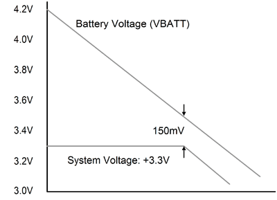
Making things more complicated is the fact that the new portable designs are more feature-rich, which translates to higher average and peak power consumption. As system current levels increase, the required headroom (see Fig. 1 ) to regulate a +3.3-V rails becomes more challenging for a given resistance between the input power source and the load (V = I x R).

Fig. 1. System headroom issues with Li-ion batteries.
Traditional buck-boost implementations
In today’s applications, addressing the need for output voltage regulation in systems with varying input voltage is accomplished with two different power architectures. The simplest way is the use of an up-front step-up (boost) converter followed by a step-down (buck) converter.
While this implementation allows for a high level of design flexibility, because of the variety of appropriate chips on the market, it has some severe drawbacks. For one, the need for two different ICs and their external components significantly increases board space and component count. Furthermore, the accumulative power efficiency of such solution is generally lower than the alternative method (EFFTOTAL = EFFBUCK x EFFBOOST ).
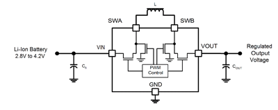
A more popular topology to achieve buck-boost functionality over the last few years is the one shown in Fig. 2 . Buck/boost ICs eliminate the need for a two-chip solution by incorporating all the circuitry required to regulate the output, independent of the input voltage level (within some limitations). This solution is more integrated and requires fewer external components, however the need to integrate four power FETs results in a larger die and therefore higher product cost.
Both of these traditional implementations do have one thing in common, and that is they can help make for a better design, but they require additional components, adding cost and taking up valuable board space. Ideally this should be implemented such that it can work from a component that is already on the board, and is already needed, combining two functions and features into a single IC.

Fig. 2. Integrated buck-boost converter.
New buck-boost implementation
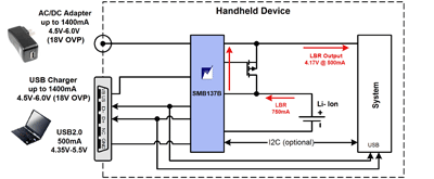
The SMB137B provides an additional power path that allows the steering of battery power to the system output either automatically or via system intervention. This additional reverse-boost operation does not require any additional external components and allows the SMB137B to function like a 4.17-V step-up regulator for the system (see Fig. 3 ).
Such an implementation is useful in cases in which a higher current is required for the system to wake-up and initiate some actions. Again, for example, if the USB power source is temporarily capable of 100-mA only (USB1 mode prior to enumeration), essential system components running the software necessary for powering up the system may not be able to power up.
In this case, the system is “trapped” and system turn-on time might be considerably long due to a very long charging process. The supplemental power from the battery via the low-battery recovery path addresses this design challenge and enables system booting even during a low-battery situation.

Fig. 3. Low-battery recovery mode.
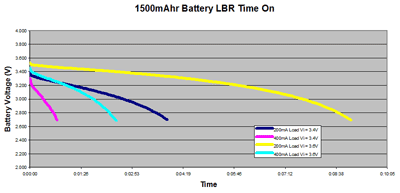
Figure 4 illustrates the benefits of the low battery recovery mode for extending system run time. In this case the test is being performed with a 1,500-mAh battery, typical of modern smart-phones. Depending on the initial battery level and the system load requirements, this buck-boost mode can extend system run time by more than eight minutes, extremely useful for a last-minute call (911) or other last-minute activities.
This extension in usable battery life can be a very powerful marketing tool for a variety of portable devices in an era where consumers demand ever-increasing system up time. The difference between the actual cell voltage and the battery pack voltage in Fig. 4 is attributed to the battery pack ESR and the system load current.

Fig. 4. Extended system run time.
Tradeoffs and benefits
The increasing complexity of modern consumer electronics, coupled with the wide adoption of Li-based batteries has introduced new challenges in power and battery management designs. Current and emerging high-capacity batteries have unused energy below the typical cut-off voltage of most portable devices, energy which until now cannot be used without the addition of expensive and large buck-boost regulators.
This becomes a greater challenge with the need for higher system currents and the use of new battery technologies. New battery charging products perform many more functions than just charging, especially during conditions in which they would otherwise be idle. They ensure that power is available whenever system needs it without the need for higher component count/cost and board space, thereby meeting the consumer demands for higher performance in slimmer and more cost-effective portable gadgets. ■
Advertisement
Learn more about Summit Microelectronics


