Improving the performance of capacitive sensors
Using signal conditioning can adjust for design tolerances and nonlinearities while eliminating environmental influences
BY GUDRUN KRAUSS
ZMD America
Madison, WI
http://www.zmdi.com
Capacitive sensors are typically cost-effective and deliver low-power performance features aligned with today’s trends for consumer and industrial applications. Capacitive sensors are cost effective because they are simple to build or already exist as a parasitic in an application. They are low power because they do not have static current, making them ideal for applications where humidity, proximity, level, fuel, position, angularity, and pressure are key characteristics.
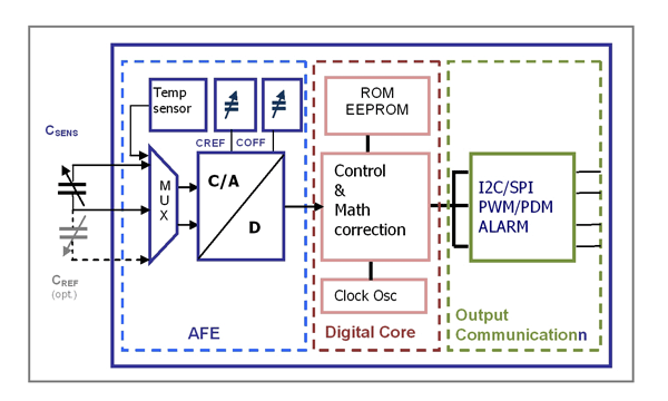
Design tolerances, nonlinearities, and unwanted environmental influences such as temperature dependence require sensor signal conditioning, including signal amplification, error correction, and removal of temperature dependency. These tasks are best mastered by using capacitive sensor signal conditioners (SSC), whose core is the analog/digital signal path (see Fig. 1 ).

Fig. 1. Schematic for typical capacitive sensor signal conditioner.
One important aspect of conditioning a capacitance sensor input signal is optimizing the capacitive-to- digital converter (CDC) input range to the sensor signal span and offset values. This issue can be addressed by integrating a trimmable internal reference and an offset capacitor.
Two steps are necessary for obtaining a precise calibration:
1. Selecting an optimum range for the CDC in order to achieve maximum resolution for the conversion.
2. Using a single-pass calibration as part of an optimized calibration method.
One method for digitizing the sensor capacity is using the sensor directly as part of a switched-capacitor network. A charge-balancing converter based on capacitor ratios is a robust solution for measuring unknown capacitance. Programmable internal capacitors allow adjusting the CDC input range to the sensor signal. In the digital core the optimum adjusted and in the CDC digitized signal is then conditioned using a set of polynomial ROM-programmed equations and the calibration coefficients stored in the EEPROM of the digital core.
A universal capacitive SSC supports different types of sensor transfer functions and offers several correction equations. Bidirectional standard digital outputs (I2 C, SPI) are necessary for preceding an end-of line calibration.
CDC range selection
For the range requirement, the CDC can be configured using gain and offset terms. The gain term is set by a programmable on-chip reference capacitor CREF and defines the capacitive input span. The offset term is set by another programmable on-chip capacitor COFF and defines the base capacitance above which the span is located.
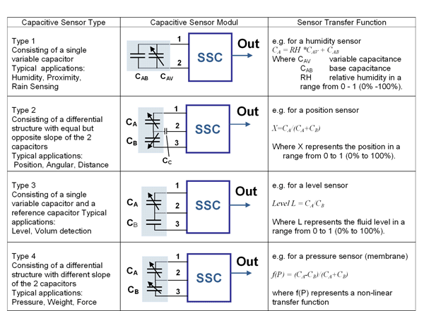
Choosing the wrong front-end configuration can cause overdrive and saturation of the CDC, or it may result in a waste of resolution that cannot be recovered by the subsequent digital conditioning. The transfer function of the capacitive sensors (see Fig. 2 ) determines the criteria for selecting the adequate CDC transfer functions 1 to 4.

Fig. 2 Four types of capacitive sensors.
Type 1 is a single capacitive sensor CA, for example, a humidity sensor. The CDC must be configured so that CAB is compensated by an offset term and RH* CAV is covered by an adequate gain term by the Type-1 CDC transfer function:
ZSENSOR = 2RES * gain * (CIN – offset) = 2RES * (CIN – COFF ) / CREF
where:
ZSENSOR is the CDC output number
CIN is the input sensor capacitance
CREF is the reference capacitance;
COFF is the offset capacitance
RES is the resolution of the CDC
The final configuration of CREF and COFF must be chosen in a way that the CDC input range is never saturated at maximum input signal including possible sensor tolerances and temperature influences.
Type 2 is the differential sensor; for example, the linear position sensor. The sensor includes two capacitors; typically the sum of the two parts remains constant. The capacitance parts are captured as a ratio. This “self-referencing” has the advantage of compensating environmental influences; for example, humidity or temperature.
For such a sensor, the CDC transfer function would be set to Type-2 CDC transfer function, which results in a digital output of
ZSENSOR = 2RES * CA / (CA + CB )
The goal of this kind of sensor type is to provide as much span as possible by keeping the parallel parasitic capacitors small (parasitics to ground are tolerable).
The capacitor CC for this sensor type does not appear in any equation and has no influence on the transfer function. It could be replaced by a short circuit, but this capacitor is attractive in two respects:
In positioning sensors, it prevents the need for direct contact with moving parts and makes the sensor very robust against wearing.CC could also be used to lower the overall capacitance level. It limits the maximum capacitance seen by the CDC to CC even if CA and CB have higher values.
Type 3 sensors are special cases of the Type-1 single-variable capacitive sensor. They have an external capacitor as part of the sensor construction which acts as a reference capacitor that adds some self-compensation for environmental influences, such as temperature and aging. Also, for the example level sensor shown, the liquid’s εrel (relative dielectric permittivity) tolerance level is compensated.
Normally for Type-3 sensor transfer function, the CDC should be set to the CDC transfer function Type-1 in order to provide a linear output of the converter that would need very little additional signal conditioning. To do this, the simple sensor design shown in Fig. 2 Type-3 must be modified to ensure that CB is always equal to or bigger than the maximum value of CA . In some cases, this could cause difficulties in the construction of the sensor or disadvantages in the application, requiring that another method must be chosen.
Using the Type-2 CDC transfer function results in a digital output for the converter of
ZSENSOR = 2RES * CA / (CA + CB ) = 2RES * L / (L+ 1)
when combined with the sensor’s transfer function. The resulting non-linearity, though it is systematic not parasitic, can be corrected in the digital domain to an overall linear response.
Type 4 is presented by a common type of pressure sensor. Here again the membrane carries two capacitors that can be seen as the “input” capacitor and “reference” capacitor. Both capacitors change in the same direction with pressure but with a different slope. The adequate CDC transfer function is defined with the output signal as
ZSENSOR = 2RES * (CA -CB )/(CA +CB )
Since the above equation is not a linear function of the pressure because of the physics of the membrane deflection, the result must be corrected for linearity in the digital domain.
Sensor data validation
The adjustment of capacitance SSC’s equation system to the individual sensor behavior occurs during calibration, presuming that the configuration of the CDC (type, CREF , COFF ) was done correctly.
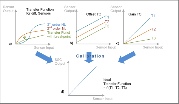
εεThe prerequisite for a precise calibration is the knowledge of the sensor characteristics. This is most effectively done as a measurement of the sensor capacitance as a function of the sensor input signal (for example, pressure or humidity) and the temperature (see Fig. 3 ).

Fig. 3. Sensor characterization: (a) nonlinearity, (b) offset TC, (c) gain TC, (d) linear temperature independent target function of the calibration.
With this data, one can estimate what type of correction (only linear or higher order) would fulfill the targeted accuracy. The raw data collection function of the capacitive SSC can be used to capture these data. Very useful for this estimation is a nonlinear optimization tool like the Microsoft Office Excel-Solver (including the trend line functionality). The following strategy has been proven:
Taking one characteristic, or 5 to 10 data points, versus the sensor input signal at room temperature (see Fig. 3a ) for three different sensor types. With these data, the required correction equation linear, second or third order, break-point can be estimated. Typical sensors with a break-point transfer function include humidity sensors, where the capacitance slope “jumped” when humidly changes from dry to more humid air.Taking one characteristic, or 4 to 8 data points, versus temperature with zero input signal. With these data, the TCO (temperature coefficient for offset) or a potential second-order TCO can be estimated again by a linear or second-order fit of the characteristic (see Fig. 3b ).Taking one characteristic, or 4 to 8 data points, versus temperature at full-scale input signal. Based on these data, the TCG (temperature coefficient of gain) or a potential second-order TCG can be estimated by including the temperature data at zero to clearly separate the TCG from TCO (see Fig. 3c ).
Finally it is worthwhile to make a full fit over the captured data by letting the Excel-Solver find optimized values for all coefficients based on the exact correction equations from the SSC specification. The result can provide a good estimation of the achievable accuracy.
Capacitive sensor calibration
Using a polynomial to model sensor behavior, calibration is a process of determining the coefficients of the equation system by using a best fit approach. If n coefficients are needed to reach the required accuracy of the calibration, then n data points (pairs of “raw” sensor input and target values) are necessary.
The target values of the calibrated output signal are usually given as percentage ratios related to the full scale output (2RES for digital outputs). For example, the target value 10% for a 14-bit CDC is 1,638 counts. Calibration includes the correction of small parasitic sensors and systematic non-linearities.
The calibration itself is characterized by three main steps:
1. Configuration data (such as CDC adjustment) including a unique ID is written to the SSC EEPROM. The ID is also the identifier for the PC stored data base.
2. Once the calibration method is selected, the minimum number of data points required for calibration can be determined. Criteria for the optimum location of these points are the target range of the sensor application and the known sensor characteristic. The data stored on the PC includes target values, raw capacitances and raw temperatures used to calculate the coefficients at the end of the calibration process.
3. After the total number of calibration points is collected, the calibration coefficients are calculated and written to the EEPROM.
This “single-pass” calibration method does not require any iteration steps or adjustment of external components. Using the bidirectional digital interface (I2 C, SPI), an end-of-line calibration of the packaged sensor module is possible.
The ZMD31210 cLite signal conditioner is one example of configuring the CDC to different transfer functions and to adjust the signal to new types of sensors. ■
Advertisement
Learn more about ZMDI


