Understanding new techniques used to capture high-speed bus signals makes choosing the appropriate instrument easier
BY BRIG ASAY
Agilent Technologies, Santa Clara, CA
http://www.agilent.com
The year 2009 saw the rise of third-generation serial busses such as USB and SATA, and 2010 will see PCIe gen3 with a data rate of 8 Gbits/s and fourth generation SAS serial bus at 12 Gbits/s. In addition to increasing data rates for serial busses, the idea of directly digitizing signals above the X-Band (25 GHz) has become more common in applications such as satellites. Optical applications operating at 100 Gbits/s and greater are becoming increasingly more popular.
Until 2007, technologies such as these required down conversion or testing with measurement equipment unrelated to real-time oscilloscopes. Now designers can use real time oscilloscope to test third- and fourth-generation serial busses, check direct- digitize signals above the X-band, and easily make 100-Gbaud optical measurements. Since several suppliers now offer bandwidths greater than 16 GHz in their oscilloscopes, using different hardware and software techniques, it is important to understand the tradeoffs they make to achieve high bandwidth.
Raw hardware performance
The most difficult way to achieve bandwidths greater than 20 GHz is through raw hardware performance. A real-time oscilloscope vendor must invest in multiple chips that are rated to these bandwidths (including the preamplifier).
Processes are need that produce a transistor cutoff frequency greater than 150 GHz; these processes are expensive and not common. For an oscilloscope vendor, the expense is even greater than computer manufacturers, as the former is unable to benefit from economies of scale. Even with the right processes, the oscilloscope supplier must be able to design in this high speed environment.
For example, for its 90000 X-Series oscilloscope, Agilent created a proprietary Indium Phosphide (InP) technology with a cutoff frequency of 200 GHz. Thus the highest bandwidth unit in the series, the DSAX93204A, achieves its full 32 GHz with no additional hardware and software techniques. As a result, the oscilloscope’s noise density is the same from 31 to 32 GHz as it is from 1 to 2 GHz. In addition to high bandwidth chips (see Fig. 1 ), the DSAX93204A uses new packaging techniques to ensure that the InP chips can run at full bandwidth without overheating.
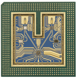
Fig. 1. This multichip module was developed for the 90000 X-Series oscilloscope.
Currently, other suppliers use silicon germanium to achieve their scope’s bandwidth; the process they are using has a cutoff frequency close to 110 GHz, so their preamplifier bandwidth is equal to 16 GHz. It is possible to achieve a 200-GHz cutoff frequency without abandoning silicon germanium. For example, IBM’s 8HP process has a 207-GHz cutoff frequency.
Chip process technologies available for oscilloscope vendors
Another benefit of developing high-bandwidth hardware performance is that the probing can use the same chip process and achieve high bandwidth as well. In the case of Agilent, its probing system achieves 30 GHz.
Raw hardware performance’s biggest drawback is that it takes significant time and investment to develop what is often referred to as true-analog bandwidth at the high frequencies encountered by oscilloscope users today. And just because an oscilloscope has hardware performance to high bandwidth, it is still very important to understand how well it was designed; the front end of an oscilloscope could still have high noise if not designed correctly.
Frequency interleaving
To achieve a 30-GHz bandwidth, some oscilloscope designers have chosen to use uses a technique known as frequency interleaving. A technique used in the RF world for many years, frequency interleaving is different than the traditional interleaving of the ADCs used by oscilloscope vendors.
All oscilloscope vendors traditionally interleave channel resources such as memory and ADCs to obtain high sample rate and deeper memory depth. For example the Infiniium DSAX93204A interleaves four 20-Gsample/s ADCs to obtain an 80-Gsample/s rate. However, until the use of frequency interleaving, the interleaving techniques were only done post acquisition and could only be tightly controlled using highly accurate clocks inside the oscilloscope.
Even so, interleaving errors still occur in today’s oscilloscopes. This causes increases in the oscilloscope’s total harmonic distortion (THD); in most cases, the increase in THD is a worthwhile tradeoff for higher sample rate.
Frequency interleaving, which requires additional hardware and advanced digital signal processing, takes this idea of interleaving to a new level. Not only does a vendor interleave after the acquisition has taken place, but during the acquisition itself. This means that a signal is actually interleaved twice during the entire acquisition process.
To understand how frequency interleaving works, consider a signal. The signal enters the oscilloscope and is immediately split by a diplexer, into multiple frequency bands — high frequency components and then low frequency components. The low frequency components are equivalent to the actual analog performance of the oscilloscope, currently limited to 16 GHz.
The high-frequency components are immediately down-converted to have frequency components that the oscilloscope hardware can handle. For example, if an oscilloscope has analog performance to 16 GHz, but the vendor uses frequency interleaving to achieve 30 GHz, then frequency components to 16 GHz would not be down-converted, but all components greater than 16 GHz will immediately be passed through the down-converter.
The two frequency components then go through significant digital signal processing to ensure the high- frequency component was correctly acquired. The low- and high-frequency components are then recombined to nearly double the analog bandwidth of the oscilloscope.
By developing the frequency interleaving technique, oscilloscope vendors can produce higher-bandwidth scopes without having to develop expensive preamplifier chips. As is the case with most techniques, there are tradeoffs that must be considered.
The biggest tradeoff is the total harmonic distortion, based on how good the interleaving technique is. All of the processing adds distortion, and the additional hardware increases the signal path and noise (see Fig. 2 ). Thus the interleaving technique trades off some measurement accuracy for increased bandwidth.
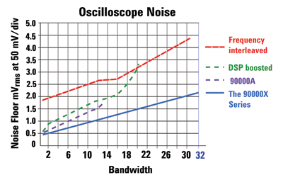
Fig. 2. Noise floor comparisons of different oscilloscopes with different techniques. The 90000 X-Series uses raw hardware.
DSP boosting
In 2004, the first 13 GHz oscilloscope used a technique known as DSP boosting to raise bandwidth from 12 to 13 GHz. At the time, many argued that the technique caused too much noise, and they did not accept the 13-GHz figure as a “real” bandwidth. However, in 2007, the first 20 GHz oscilloscope DSP boosted from 16 to 20 GHz. Suddenly the arguments against DSP boosting seemed to ease, as two major vendors were now “boosting.” But, more importantly, it was then the only way to achieve a 20-GHz bandwidth.
The first 20-GHz oscilloscope was very well received in the market, as designers now could make higher bandwidth measurements on 6- and 8-Gbit/s signals. They purchased the oscilloscope based only on the banner specification, without worrying about the technology underlying it.
So what is DSP boosting? DSP boosting is a processing technique in which the high-frequency content of an oscilloscope is pumped with software. One important point to note is that DSP boosting needs to be distinguished from other types of DSP correction that oscilloscope vendors use today.
To understand DSP boosting, first remember that a signal can be broken down into its numerous frequency components. Using software, you can amplify the higher-frequency components of the signal. In Fig. 3 , the red trace represents a typical oscilloscope frequency response. The green trace is the result of using a software filter to amplify the high-frequency components, which results in the increased bandwidth.
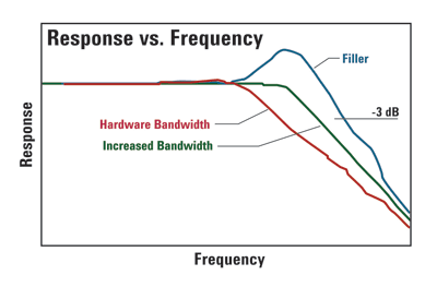
Fig. 3. Software can be used for DSP bandwidth-enhancement filtering.
At this point everything looks just fine. But there is one major drawback: when the signal is amplified, so is the noise contribution of the oscilloscope. Depending on how much boosting is done, the technique could actually degrade the signal and give worse results than a lower-bandwidth, non-boosted signal.
This is the single most important reason to really analyze how much boosting is occurring and whether the bandwidth-noise tradeoff is acceptable. Figure 4 shows the effects of DSP boosting from 16 to 20 GHz on the noise of an oscilloscope. This increase in noise has a direct impact when measuring circuit performance (see Fig. 5 ).
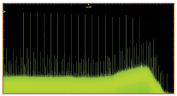
Fig. 4. In this sine wave sweep with DSP boosting, note the noise “boost” at high frequency.
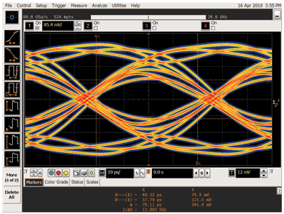
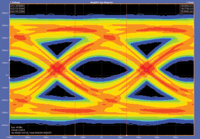
Fig. 5. Using a 10.3125-Gbit/s industry standard PRBS7 pattern signal with ISI added, measurement performance using of raw hardware (top) and DSP boosting (bottom) is compared. The raw hardware performance yields over 25% more eye height and width.
Selections considerations
In looking to select a scope, the banner specification alone is not the ideal way to measure an oscilloscope’s suitability. Oscilloscope vendors use various techniques to achieve high bandwidth, and these techniques come with tradeoffs that may be detrimental to measurement accuracy. Accuracy is not free, and so users should expect to get what they pay for.
If one has a choice between scopes with raw hardware bandwidth or a bandwidth created through DSP techniques, such as boosting or frequency interleaving, a rule of thumb is that the one with raw hardware bandwidth will likely be more accurate. However, designers should investigate even the most technically advanced oscilloscopes — checking the noise floor, jitter measurement floor, and so forth — to find the one that best suits their needs. ■
Advertisement
Learn more about Agilent Technologies


