Virtual remote sensing improves load regulation
A virtual remote sensing tool helps get accurate load voltage regulation over highly resistive interconnections
BY ROBERT DOBKIN
Linear Technology, Milpitas, CA
http://www.linear.com
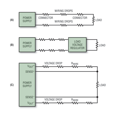
Wires and connectors have resistance. Ohm’s law is unavoidable and dictates that a power source’s remote load voltage will be less than the source’s output voltage. The conventional solution to improving regulation at the load side involves adding extra wires for remote sensing but adding extra wires is not always desirable, or possible. Other solutions, such as a remote regulator to maintain a regulated voltage at the load are costly. Figure 1 shows the line drops and prior correction methods.

Fig. 1. (a) Power supply with line drops. (b)Line drops corrected by a second regulator. (c)Virtual remote sensing, using additional wires.
A new control method, virtual remote sense (VRS) maintains the correct load voltage with changing loads and wire drops without extra sensing wires. It replaces and avoids the pitfalls of conventional solutions, and in some instances solves the previously insoluble. The LT4180 is designed as a controller that supplements the controller in an existing IC or modular power supply.
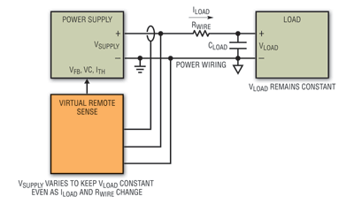
The basic control loop is shown in Fig. 2 . VRS solves this problem by interrogating the line impedance and dynamically correcting for the voltage drops. It alternates the output current between 95% of the required output current and 105% of the required output current. In other words, the LT4180 forces the supply to provide a dc current plus a current square wave with peak-to-peak amplitude equal to 10% of the dc current. Decoupling capacitor C (which normally ensures low impedance for load transients in non-VRS systems) assumes an additional role by filtering out voltage transients from the VRS square wave.

Fig. 2. LT4180 basic connections for virtual remote sensing.
Because the supply in Fig. 1c is sized to produce an “ac short” at the square-wave frequency, a square wave voltage is produced at the power supply equal to: VSUPPLY(ac) = 0.1 x Idc x R, measured in Vp-p. The square wave voltage at the power supply has a peak-to-peak amplitude equal to one-tenth the dc-wiring drop. This is a direct measurement of wiring drop, not an estimate, accurate over all load currents. Signal processing produces a dc-voltage from this ac-signal which is introduced into the supply feedback loop to provide accurate load regulation. Note that the “power supply” may be an IC linear or switching regulator, a module or any other power source capable of variable output.
Power supplies can be synchronized to the LT4180 and VRS interrogation frequency is adjustable over more than three decades. Optional spread spectrum operation provides partial immunity from single tone interference and a 3 to 50-V input range expands the applications range.
Because this technique is based on a calculation of load voltage, not a direct measurement, the resultant correction is an approximation, but a very good one. Consider the case where the load current with a 5-V output is increased from zero until it produces a 2.5-V wiring drop. A voltage drop equivalent to 50% of load voltage results in only a 1.5% shift in load voltage value. Smaller wiring drops produce even better results.
Applications
Increase high-lighting efficiency
While incandescent lighting is on the decline, high intensity halogen lights continue to be popular. The operating voltage of halogens directly affects their light output, efficiency, lifetime and color temperature as follows:
• Light output is approximately proportional to V3.4
• Power consumption is approximately proportional to V1.6
• Lifetime is approximately inversely proportional to V16
• Color temperature is approximately proportional to V0.42
Normally these devices run at 12 V, but at relatively high current, so line drops can also be high, with the load-end discrepancy easily reaching one or more volts. A 12-V halogen operated at 11 V produces 25% less light than when operated at the correct voltage, while only saving 13% power. For a fixed light level, 25% more bulbs need to be used if the voltage is allowed to droop to 11 V. Running halogens at the correct voltage offers more precise lighting control.
A SEPIC-based automotive halogen headlight power supply (see Fig. 3 ) improves bulb reliability while also insuring optimum illumination. The design maintains 12 V at the bulb over a 9 to 15-V input voltage range. It works well up to 1-Ω interconnection resistance. Using VRS allows the SEPIC converter to be placed far from the load, away from extreme environments, thus improving reliability.
Residential and commercial track-style lighting also benefit. The cost of properly regulating lamp voltage is quickly paid back in the form of lower power consumption and higher efficiency. Two to three kilowatt-hours may be saved in a day on a 250-W string while maintaining the same amount of light. Color temperature (while not as dependent on voltage as other lamp parameters) also benefits. VRS allows remote voltage regulation of a single lamp, or provides first-order regulation of several lamps distributed over a wire.
The LT4180 enables the use of virtual remote sensing for accurate load voltage regulation over highly resistive interconnections. Virtual remote sensing provides alternatives previously unavailable for simplifying or improving designs. The LT4180 VRS works with virtually any power supply or regulator: switching or linear, isolated or non-isolated, synchronized or unsynchronized. It contains a VRS regulation circuit and a variety of features such as undervoltage and overvoltage lockout, and optoisolator drivers. ■
Acknowledgement : The author wishes to thank Tom Hack and Jim Williams for the design, applications, and portions of this article.
Advertisement
Learn more about Linear Technology


