When good video goes bad and what to do about it
BY BILL BOLDT
Fairchild Semiconductor
South Portland, ME
http://fairchildsemi.com
Video is obviously far more sophisticated now than when Philo Farnsworth demonstrated a working electronic scanning television in his San Francisco lab in 1928 because video has gone digital. Despite consumer inertia related to a gigantic installed base of analog televisions, the conversion to digital video is now fully underway. The fabled convergence of computers and television, which has been predicted for decades is becoming a reality because computers and video equipment both now live in the same mathematical universe: that is, the digital domain (although there is some analog at its edges to make sure humans can participate).
To navigate between the human-analog domain (the world of sound and vision) into the mathematical Digital Signal Processing (DSP) domain of modern video, electronic equipment must deal with the nuances of the analog/digital interface. Among the major analog/digital interface issues are (1) the need to comply with the laws associated with the digitization process itself, and (2) the effects of real world electronic interference. These are related. Video filter components address these particular issues in a cost effective and practical way, and make a big contribution to the quality of the modern video experience.
So, why does video equipment need a filter? The answer is to make sure that unwanted signals get eliminated (that is, filtered out) allowing only the intended signals to get through. Filters are used in two ways: (1) as low-pass output filters prior to the analog back-panel output connectors, and (2) as reconstruction filters prior to an A/D converter. The technical aspects of the latter are described here by focusing on two very fundamental causes of video signal problems: sampling artifacts and external interference.
Sampling artifacts
Sampling artifacts stem from the process of digitization. Digitization is now endemic because video signals must be processed digitally to achieve high levels of resolution like Enhanced Definition (ED), High Definition (HD) and 1080p High Definition demanded by consumers. Digitization also enables transmission of and storage of large amounts of video by using digital signal compression. Digitization is also the key to preservation of signal quality because digital processors can recreate the original analog signal from the received analog signal that has degraded during transmission.
Just as taught in communication theory classes, degradation of an analog signal is inevitable in any real world transmission channel. Figure 1 shows a degraded analog signal getting restored to its original state by digitization, digital signal processing, and reconstruction. Due to its ability to completely reproduce the intended signal, digitization is at the core of what makes the modern video experience possible.

Fig. 1. Digitization, processing, and reconstruction
To “go digital” certain key mathematical laws must be obeyed, because video digital signal processing is mathematics made into visible reality. If the laws are not followed it becomes obvious to any viewer. Arguably, the most fundamental and practical mathematical law of digitization is the Nyquist Theorem (sometimes called the Nyquist-Shannon Theorem) which states that to accurately reproduce a digitized signal, the sampling frequency must be more than twice the total bandwidth of the intended video signal. Stating this in mathematical terms: fs 2fc , where fs is the sampling frequency and fc is the highest frequency contained in the signal.
Looking at a simple sine wave it is easy to see how sampling at too low a rate fails to represent the intended signal leading to another signal: the “alias” (see Fig. 2 ).
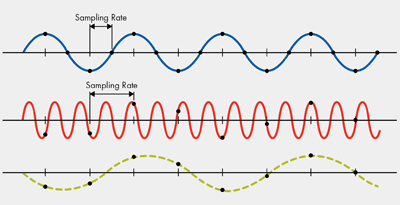
Fig. 2. Undersampling a sine wave causes an alias
Failure to comply with this most basic of requirements produces the aliasing phenomenon, which presents as moiré patterns (frequency to frequency beating patterns) on the video screen. This is seen as unsightly distortion, and must be avoided. To explain what a moiré pattern is, the most basic example is two sets of parallel lines slightly angled on each other as seen in Fig. 3 . It shows a visual pattern popping out that does not look like the original lines but a completely new pattern all together: a moiré pattern.

Fig. 3. Simple moiré pattern formed from two sets of parallel lines.
On the positive side, the moiré effect has been used for ages in textile design (see Fig. 4 ) and is also used in graphic arts (see Fig. 5 ) to create attractive and interesting visual patterns.
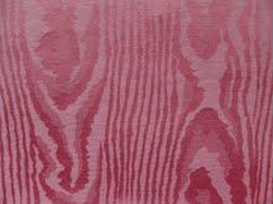
Fig. 4. Moiré pattern made of silk.
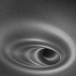
Fig. 5. Moiré patterns are used in graphic design.
But right there the positive part comes to an abrupt end. In video reproduction and photography there is nothing positive or attractive about moiré patterns. They create distortion such as false color and ripple effects that need to be “filtered” out (see Fig. 6 ).
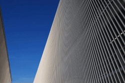
Fig. 6. Ripple distortion on a video signal caused by moiré effects To fight aliasing the signal must be sampled at the correct frequency to obey the Nyquist Theorem, and there must also be a reconstruction filter and an anti-alias filter to remove unwanted signals that are naturally created by digitization and reconstruction. The input anti-alias filter comes before the ADC and the reconstruction filter after the DAC. When the video output is converted back to analog, the signal becomes a series of small stair steps because the DAC output is held at a fixed level between the sampling clocks. The output spectrum contains the video and the clock and image sidebands spaced around the clock frequency. The reconstruction filter attenuates the clock and images to smooth out the little steps to remake the video signal. Figure 7 shows the FMS6151 integrated video filter acting as a reconstruction filter between the host digital processor and the output jack of the video source
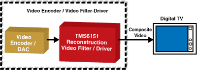
Fig. 7. FMS6151 video filter acting as a reconstruction filter.
External Interference
If the filtering is poor or the layout is inadequate thus allowing ingress of external interference, then moiré effects can show up. As an instructive example, external interference can come from poor transmission cable grounding, which invites frequencies to mix in from RF sources such as broadcast radio stations, CB radios, or commercial mobile radios. Also, interference can come from digital clocks and image frequencies that have not been adequately removed (filtered) from the analog video input signal prior to A to D conversion.
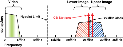
Fig. 8. Example of a video signal subject to corruptive sources.
Figure 8 shows a corrupted signal coming from a DVD player with a poor reconstruction filter that did not adequately suppress the image frequencies and RF interference injected through a coax transmission cable with poor grounding. We will use this example to illustrate the mechanism of folding of the spectrum about the Nyquist frequency limit and clock, which is a serious cause of signal corruption.
When the signal in Fig. 8 is redigitized with a second 27-MHz sampling clock, the result is noted in Fig. 9 . The image sidebands around the clock get folded around the Nyquist and zero frequencies to produce unwanted signal aliases on top of the desired video signal.
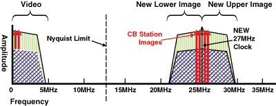
Fig. 9. Redigitization. Furthermore, the radio and high-frequency images get intertwined with the baseband video signal. Figure 10 demonstrates the folding action.
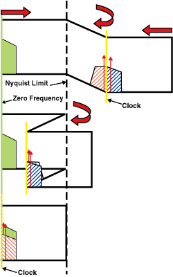
Fig. 10. Aliasing from folding around the Nyquist and zero frequencies.
The folding action inverts the frequencies of the lower image and places them on top of the baseband video. Additionally, the spectrum also folds with the clock and zero frequencies making the upper image sideband appear as well on top of the video baseband. Once the video contains such an alias it becomes a permanent part of the video signal and cannot be extracted downstream. The signal shown in Fig. 8 will result in a video picture filled with distortion in the form of ugly herringbone, flashing, and streaks correlating with the external radio signals. Furthermore, because the aliased image sidebands have undefined phases, the baseband video’s lower- and upper-image high-frequency edges add and subtract randomly with each other at each instant causing the high-frequency edges in the video to appear on the screen as shimmering, shaking, and wiggling. To make matters worse, jitter gets multiplied creating a continuously changing left-right shimmering on the edges. Because the unwanted interference is now baked into the baseband signal, a reconstruction filter can do nothing at this point to help. Therefore it is imperative to deal with such issues prior to the ADC. That is the point at which a video reconstruction filter can be applied.
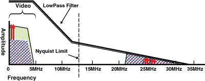
Fig. 11. The resulting corrupted video output when an adequate reconstruction low-pass filter is not used.
In Fig. 11 , the same conditions apply as in Fig. 8, but a low-pass antialias filter is applied to suppress the image, clock, and RF signals prior to A/D conversion.
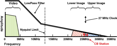
Fig. 12. Application of a proper reconstruction filter.
A video filter can provide the necessary amount of filtering for high-quality video, as shown in Fig. 13 , which illustrates the spectrum after the television’s A/D converter. The images, clock, and radio signals are suppressed to the point of being invisible to the viewer, which is the whole idea.
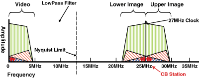
Fig. 13. The sampled signal spectrum with proper reconstruction filtering.
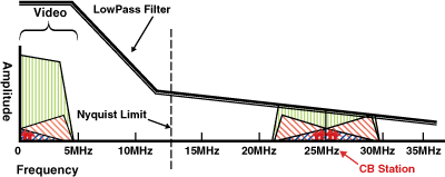
Fig. 14. The video output when a reconstruction low-pass filter is used.
Contrasting Figs 11 and 14 illustrates the need to provide adequate filtering, and this picture pretty much says it all: Filtering (and respecting the math) makes the signal much better.
Fortunately, IC companies such as Fairchild Semiconductor supply a wide range of cost effective integrated circuit video filters that come in small packages (particularly for mobile platforms); support Standard Definition (SD), Enhanced Definition (ED), High Definition (HD) and 1080p High Definition; provide various channel counts, operate with 3- or 5-V supplies, offer ESD protection, and enable low-power standby operation (for example, for Energy Star compliance).
Advertisement
Learn more about Fairchild Semiconductor


