Testing for grid-tied solar system inverters
Inverters designed for grid-tied solar systems must be tested for conformance with a range of conditions
BY ERIC TURNER
AMETEK Programmable Power, San Diego, CA
http://www.programmablepower.com
Residential and commercial solar energy systems are rapidly emerging as a “green” alternative to utility-supplied power. Grid-tied solar systems provide the user with the means to actually sell power back to the utility. The inverters in this application must be designed to accommodate a wide variation in the availability and quality of power from the solar panels; a wide variation in the size and characteristics of the load being supplied; and variations in the inter-connected “public power” source .
Ensuring that inverters are up to the task, requires comprehensive testing during development and production. This article describes a testing strategy that integrates devices to:
Simulate the solar arrays to confirm the inverter’s capabilities to determine and operate at the maximum power point (MPP),Simulate the variability of the load to confirm the inverter’s ability to handle load changes, transients, power factors and other characteristics.Simulate the interface to the grid to confirm the inverter’s ability to work harmoniously and safely with the power grid under normal conditions as well as when presented with anomalous situations such as power interrupts and brownouts.
Solar array simulation
Solar arrays operate in an uncontrolled environment. The output is highly dependent on a range of conditions including the intensity of the sunlight (full sun vs. cloudy conditions), ambient temperature, external shading effects (from tree branches or chimneys), dust, bird droppings and other factors. All of these elements affect the capacity of the solar array to produce power.
The inverter must be designed to allow for maximum power transfer from the solar array to the inverter. This so-called MPP is most commonly determined on a continuous basis. Most PV inverters are designed to harvest the maximum amount of energy available from the PV array at any point in time. To do this, they typically use a MPP tracking control algorithm to continuously present the optimum load to the PV array for maximum power transfer.
The testing of inverters for this application (both in development as well as in production) requires a power source a Solar Array Simulator (SAS) that can reliably simulate actual performance. And with virtually hundreds of solar array panels available in the marketplace, this can be a daunting requirement.
Fortunately, the National Renewable Energy Laboratory (NREL) maintains a Solar Advisor Model (SAM) database, which catalogs key parameters (for example, Voc, Isc, Vmpp at 24C and standard 1,000-W/m2 isolation) for hundreds of commercially available PV products. The SAM provides powerful tools to aid designers predict system performance for virtually any fill factor or solar material. A solar array simulator with the ability to access this data and incorporate it into a realistic, dynamic, interactive test of the inverter can pay big productivity dividends.
Many solar inverters generate ac ripple on their dc input, which is connected to the photovoltaic array. For single phase inverters, the frequency of this ripple is twice the line frequency (120 Hz for U.S. models). The simulator’s power supplies must not suppress this ripple as a function of their regulation loop.
An increasing number of inverters (and virtually all micro-inverters) accurately measure amplitude and phase of the ripple voltage and current to quickly track the MPP of the array. This approach allows tracking the MPP at a much higher speed when compared to conventional dithering techniques (also called perturbate-and-observe).
Faster tracking of the MPP results in a much higher overall efficiency in cloudy conditions, where the irradiance is constantly changing. It is likely that all solar inverters will use this approach in the near future, since end users are very sensitive to the overall efficiency of their solar energy installations. To satisfy this requirement, the PV simulator must be capable of reproducing the voltage / current behavior of a solar array even in the presence of this ripple.
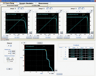
A further refinement of this process is providing the ability to simulate the MPP for multiple strings of solar panels as most installations use a large number of panels. Figure 1 shows a sample display from the AMETEK TerraSAS configured to simulate multiple strings. The MPP of the combined output of these three panels is shown as the yellow point on the lower graph.

Fig. 1. A sample display from the AMETEK TerraSAS configured to simulate multiple strings.
Load simulation and line interaction
Under typical operating conditions, the output of the solar inverter is powering loads that would normally be powered from the utility source. These grid-tied inverters can also supply excess power back to the utility. However, the performance, operation, testing and safety of interconnection products and services, must meet the requirements of IEEE 1547.
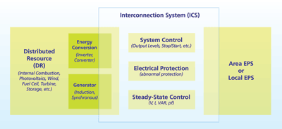
To properly test an inverter then, it is necessary to simulate the interconnection of the inverter, with its distributed resource (DR) input such as a solar array, to an electric power system (EPS). The simulation testing must be able produce the anomalous grid conditions and situations required to ensure that the inverter fully meets the requirements of the standard (see Fig. 2 ).

Fig. 2. Simulation testing must be able produce the anomalous grid conditions and situations required to ensure that the inverter fully meets the requirements of the standard.
For example, one of the problems that can occur if the interconnection is not established correctly is a situation called islanding. As defined in IEEE 1547, islanding is “a condition in which a portion of an Area Electric Power System (EPS) is energized solely by one or more Local EPSs through the associated point of common coupling (PCC) while that portion of the Area EPS is electrically separated from the rest of the Area EPS.”
Since unintentional islanding of a distributed power source may cause power quality issues, interference with grid protection devices and other problems, an anti-islanding function in equipment ensures the detection of electrical islands and proper disconnection from the electric power system. As noted, the grid source used for these tests must be capable of simulating an islanding event to ensure that the inverter under test responds appropriately.
Since the utility line power in most industrialized nations typically has distortion levels of 3% to 5% with voltage fluctuations and dips easily exceeding 10% on an almost daily basis, an alternative power source is required for these tests. To further complicate the testing process for global products, the variations of utility voltage, ranging from 120 V at 60 Hz in North America to 220/230 V at 50 Hz in most of Asia, South America, and Europe, or 100 V at 50/60 Hz in Japan, make programmability an essential feature of the power source.
A programmable bidirectional power source / sink can be used to simulate the interconnection of the inverter with the grid. This equipment can simulate utility power variability (voltage, frequency, harmonic distortion) necessary to test the inverter’s ability to source energy to the grid. In addition, the unit can dynamically test the inverter’s ability to comply with the anti-islanding tests required of grid-tied distributed resources. An added advantage of this approach is that a considerable amount of the energy used to test the inverter can be returned to the grid.

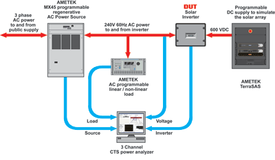
Fig. 3. A comprehensive and energy efficient means of testing devices.
Surrounding the inverter with programmable devices to simulate the output of solar arrays, simulate the loads applied to the output of the inverter and simulate the interface with the grid provides a comprehensive and energy efficient means of testing these devices. Figure 3 is an example of a comprehensive testing system. ■
Advertisement
Learn more about AMETEK Programmable Power


