Primary-side regulation drives up efficiency
A PSR charger achieves a small form factor, low standby power, and high efficiency
BY PETER HSIEH, LEON LEE, and KEVIN HSUEH
Fairchild Semiconductor, San Jose, CA
www.fairchildsemi.com
Global attention continues to focus on the methods for achieving low power consumption and high efficiency. Lighting represents nearly 20% of the worldwide consumption of electrical resources and advancements in lighting can have a tremendous impact.
LED solid-state lighting (SSL) is environmentally friendly for the global environment. It has a smart form factor, long life, high conversion efficiency, and substantially reduces power consumption up to 80% or 90% compared to traditional incandescent lighting.
LED drivers play an important role in LED SSLs, as these drivers provide accurate current to maintain a stable brightness. However, the traditional approach of the LED driver used a secondary feedback circuitry for driving LED’s voltage and current. This secondary feedback circuit increases the cost and size.
This article describes a patented primary-side regulation (PSR) technology. This PSR controller precisely regulates the voltage and current of the LED driver in the primary side of the transformer without the need for secondary feedback circuitry. It includes a frequency-hopping technique to reduce EMI and a green mode function to reduce standby power losses. With this approach, a PSR charger can achieve a smaller form factor, lower standby power and higher efficiency compared with conventional designs, such as ringing choke converter (RCC) and traditional PWM.
HB LED driver
LED lighting has many advantages but without the correct voltage and precise current, they cannot only decrease the lifetime but also increase power losses, heat consumption and ultimately, cause irreparable damage to the LED. The physical property of LED is like a general diode in that it has a sharp V-I curve.
The LED operating voltage is very sensitive to the operating current and impacts the HB-LED unit lifetime when it changes widely. Therefore, the LED current is very important to lighting illumination. For this reason, the PSR with outstanding constant-current control technology is important and instrumental for the longevity of the HB-LED unit. Typically, nonisolated buck converters or isolated flyback converters are used in LED drivers.
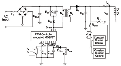
An offline constant output current LED driver for a conventional LED control circuit can be implemented using an isolated flyback converter with secondary circuit to achieved output current regulation as shown in Fig. 1 . The LED current is measured through a current-sense resistor RO from the secondary side and provides the necessary feedback information through an optocoupler. The optocoupler forms isolation for the primary and secondary side and couples the feedback signal to the PWM controller at the primary side.
To achieve better output regulation, the PWM controller receives the feedback single from secondary site through the optocoupler to decide the MOSFET duty cycle. This approach provides precise current control, but it has a higher device count, which means more board space is required, has a higher cost, and lower reliability.
Additionally, the current-sense resistor RO will also increase the power losses and decrease the efficiency of the power supply for constant current regulation. Recently, efficiency and power-saving requirements have become more important for LED drivers. Smaller size is also needed for LED applications. Hence, the conventional circuit will no longer meet this requirement. The primary-side control method can reduce device counts and provide better efficiency.

Fig. 1. Conventional secondary side regulation flyback converter for an LED driver.
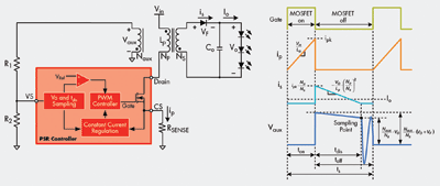
The PSR technique is an optimal solution to minimize the costs for off-line LED drivers and provides precise current control without using an optocoupler at a secondary site. The PSR concept uses an innovative method to detect the output information by auxiliary winding without feedback circuit and takes the place of an optocoupler from a secondary site as shown in Fig. 2 , which shows the basic circuit diagram of a flyback converter using a primary-side controller and its principal operation waveforms.

Fig. 2. A basic circuit diagram of a flyback converter using a primary- side controller and its waveforms.
When the PSR controller turns on the MOSFET, the transformer current iP will increases linearly from zero to ipk as Eq. 1. During the turn-on period the energy is stored in the transformer. When the MOSFET turns off (toff), the energy stored in transformer will deliver to the output of the power converter through the output rectifier. During this period, the output voltage VO and diode forward voltage VF will be reflected to the auxiliary winding NAUX, the voltage on the auxiliary winding NAUX can be expressed by Eq. 2. A proprietary sampling technology is applied to sample the reflected voltage. The correlated output voltage information can be obtained because the forward voltage of the output rectifier becomes a constant. After that, the sampled voltage compares with a precise reference voltage to develop a voltage loop for determining the on-time of the MOSFET and regulating an accurate constant output voltage.

(1)

(2)
where LP is the primary winding inductance of the transformer; VIN is the input voltage of the transformer; ton is the on time period of the MOSFET; NAUX /NS is the turn ratio of the auxiliary winding and secondary output winding; VO is the output voltage; the VF is the forward voltage of the output rectifier.
This sampling approach also duplicates a discharge time (tDIS ) of the transformer as shown in Fig. 2, the output current IO is related to secondary side current of the transformer. It can be calculated by the signal ipk, tdis as Eq. 3. The PSR controller uses this result to determine the on-time of the MOSFET and regulate a constant output current. The current-sense resistor RSENSE is used to adjust the value of the output current.

(3)
where tS is the switching period of the PSR controller; NP /NS is the turn ratio of the primary winding and secondary output winding; RSENSE is the sense resistance for converting the switching current of the transformer to a voltage VCS .
Using a PSR controller
An HB LED driver can be used to drive three HB LEDs in a series so that the output specification is 12 V/0.35 A. By using the FSEZ1016A PSR controller, which integrates a PSR controller and a 600-V/1-A MOSFET, will help reduce external components, PCB size, power losses, signal noise on the MOSFET’s driver circuit, and will also reduce interference.
To minimize standby power losses, the proprietary green-mode function provides off-time modulation to decrease the PWM frequency linearly at light-load and no-load conditions to easily meet the most of green requirements. The built-in frequency-hopping function further improves EMI performance.

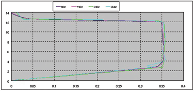
Fig. 3. V-I curve by using PSR controller.
This experiment shows constant-current (CC) design can achieve 1.8% regulation with 4-V foldback voltage (shown in Fig. 3), is suitable for a wide range VDD , and the CC capability is relative to the output voltage. The efficiency was 77.66% at 115-Vac input and 77.40% at 230-Vac input, and a no-load power saving of 0.115 W. By using FSEZ1016A, a lighting solution can be implemented with the fewest external components and to minimize cost. ■
Advertisement
Learn more about Fairchild Semiconductor


