Control methods provide good efficiency combined with ease of implementation
BY ERIC HARDT
Zilog
www.zilog.com
Many different types of induction motors have been available on the market for decades, including ac induction, brushed dc, and brushless dc (BLDC) motors. Each type has advantages and disadvantages. The dc brushed motors are easier to operate, but tend to require more maintenance. The ac induction motor and dc brushed motors tend to be not as efficient under many operating conditions. The brushless dc (BLDC) motor requires more intelligence to operate, but tends to be virtually maintenance-free, and the controller’s intelligence provides the ability to run at optimum efficiency under all load conditions.

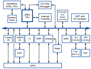
Fig. 1: The Z16FMC series of motor control MCUs have 128 Kbytes of flash, 4 Kbytes of RAM, DMA, and a 12-channel 10-bit A/D converter.
Worldwide, industries are growing more demanding of efficiency and sophistication in BLDC motor drives. BLDC motors are found in white goods, automotive, cooling, aerospace, medical, and industrial automation each with specialized operational requirements. To meet these requirements, microcontrollers offer the flexibility and ease of implementation to meet the most stringent design requirements.
MCU-based solutions
Many MCU-based solutions are available, using 8-, 16-, and 32-bit MCUs. Most solutions promote cost-sensitive and fast time-to market designs. Some microcontroller architectures, combined with the implementation of efficient firmware algorithms, allow for reliable three-phase BLDC motor control at a relative low MIPS rate, which is important because, if design constraints allow it, running an MCU at the lowest possible clock frequency allows for less power consumption and in most cases, fewer EMI-related problems.
The BLDC motor can be operated in either single-phase or three-phase mode. The three-phase operation provide generally higher efficiencies, higher torque, less ripple current, less electrical noise, and higher life expectancies with less wear and tear on ball bearings and electrolytic capacitors. They are operated either with or without sensors. Sensor operation uses Hall sensors in 30, 60, 90°, or 120 separation. Sensorless operation uses the back electro-motive force (BEMF) to detect the zero-crossing information and identify the current commutation step.
The sensor version can be implemented with simple firmware algorithms because the BLDC rotor position information is readily available upon startup, but this version comes with higher cost and additional manufacturing steps. The sensorless version requires a greater familiarity with BLDC motor physics to implement reliable firmware because the motor needs to go into the startup phase until the speed is high enough to obtain the generated BEMF zero-crossing information for further commutation. The sensorless version has the benefit of less wiring, lower BOM, and lower manufacturing cost.
There is a further distinction in the commutation scheme. Designs may use either trapezoidal, sinusoidal, or space vector control. The space vector control method will use up to 95% of the bus voltage, whereas trapezoidal and sinusoidal use about 90%. For most BLDC applications, the trapezoidal and sinusoidal method suffice. The space vectors’ increased bus voltage utilization yields higher efficiency. However, space vector use requires a steep learning curve due to complex math-intensive software algorithms and longe time-to-market cycles.
To commutate a BLDC motor in a sensorless design, three comparators detect BEMF zero crossing and compute the next commutation step. This method requires a defined current during a “forced ramp up” period.
Some motor control solutions require only the combination of one 16-bit timer and one A/D converter module for reliable BLDC operation, keeping the program heuristic simple and fast and enabling the motor to start up smoothly to demand speed. In many cases, this eliminates the need for a startup ramp, soft-start or startup overcurrent protection.
Motor control solutions should allow for quick evaluation of motors with different operating voltages and speeds, while an on-chip discrete comparator is used for cycle-by-cycle PWM shutdown in case of an overcurrent event. The control MCU must be able to guarantee excellent response time to protect the application.
Six dedicated PWM-modulated I/O ports are used to steer the three-phase motor’s commutation in independent or complementary mode. Complementary mode has gained popularity with applications that use regenerative breaking. Zilog has recently announced the Z16FMC family of 16-bit MCUs, which provide a four-channel linked-list DMA and automated interoperation between the A/D, the timer, the comparator, and the PWM outputs, therefore providing near-real-time processing. ■
Advertisement
Learn more about Zilog


