Single- and multi-touch user interface development dates from the early 1970s, although the technology achieved first notable implementation prominence when Apple unveiled the capacitive touch-based first-generation iPhone in January 2007. Since then, touch interface-centric designs have widely proliferated not only to other mobile electronics devices but also across a diversity of applications, drafting off the volume and cost efficiencies of the consumer electronics market.
Although the fundamental concept of a touch sensor is relatively easy to grasp, several different implementation options exist, each with a unique set of strengths and shortcomings. Evolving user requirements are also upping the ante for vendors’ product specifications, to some degree counteracting the steadily increasing number of suppliers entering the market over time.
Button basics
Modern touch buttons (also commonly referred to as switches) promise higher reliability through extended-use life than their mechanical forebears, along with delivering a futuristic-feeling usage experience. A resistive touch button, also known as a membrane button, employs a straightforward assemblage (Fig. 1a). Upper and lower contacts, the former mounted to a flexible membrane, are normally kept separate by spacers. Depressing the membrane creates a short circuit between the two contacts (Fig. 1b). Material and construction variation can create (or, if desired, suppress) tactile feedback indicating a successful button press.
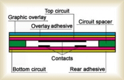
Fig 1a

Fig 1b
Capacitive touch buttons also harness flexible membranes in their upper construction layers, but they leverage a different electronic implementation (Fig. 2a). In this particular case, the upper and lower contacts form the two plates of a capacitor; bringing them more closely together (or conversely, further apart) alters the capacitance sensed by the connected system, which subsequently takes appropriate action at particular measured-value thresholds.
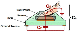
Fig 2a
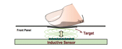
Fig 2b
With inductive touch, the upper conductor is replaced by magnetic material, with the lower sensor wound into a coil-shaped structure (Fig. 2b). As English chemist and physicist Michael Faraday discovered in the early 1800s, a varying magnetic field moving through a conducting coil generates an electrical current in that coil. Codified as Faraday’s Law, the concept of electromagnetic induction is at the core of this particular button implementation.
Resistive touchscreens
Extrapolate a single membrane button to a switch array located in front of a display, and you’ve comprehended the elementary concept of a resistive touchscreen (Fig. 3a). Instead of discrete top layer- and substrate-mounted contacts, a touchscreen coats the entire underside of the former and topside of the latter with thin-film conductive layers. A dedicated-function controller historically found use as the means of decoding touch location data and passing it along to the system, although this facility is increasingly being instead integrated within the system microcontroller or SoC.
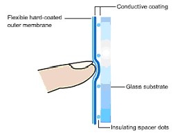
Fig 3a
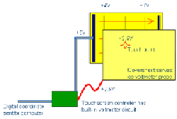
Fig 3b
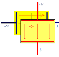
Fig 3c
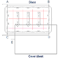
Fig 3d
Whereas an opaque structure is often sufficient for a single- or few-button front panel arrangement, a touchscreen must allow the user to clearly view the underlying displayed information. As such, near-translucent ITO (indium tin oxide) most commonly finds use as the conductive material bonded to both the transparent outer layer and see-though substrate. However, ITO’s limited sourcing options combined with its costly, time-consuming and environmentally damaging manufacturing process, sometimes leads to the substitution of AZO (aluminum zinc oxide) or another metallic film. Alternative compounds, including carbon-based nanotubes and graphene along with conductive polymers, are also under development with promising early results.
In a conventional four-wire resistive touchscreen implementation, the controller first applies 5V to the back layer (Fig. 3b). Upon detecting a touch event, it probes the voltage via the cover sheet, reading a gradient representing the left-vs-right (x-axis) position. The controller then applies 5V to the cover sheet, now probing from the back layer to determine an up-vs-down (y-axis) position (Fig. 3c). Only three of the four wires (5V, ground, and probe) find use at any point in time. The approach is simple to implement from both algorithm and hardware standpoints, but it requires both initial calibration and periodic re-adjustment, and it’s inherently touch activation count (i.e. lifetime)-limited. The constant flexing of the outer cover sheet with use sooner-or-later creates microscopic cracks in the ITO coating, altering its electrical impedance and degrading this particular axis’s linearity and accuracy.
The five-wire resistive touchscreen somewhat alleviates these issues, albeit with a higher BOM (bill of-materials) cost (Fig. 3d). One wire goes to the cover sheet, which acts as the voltage probe. Four wires go to the corners of the back glass layers. The controller first applies 5V to the two top corners and grounds the bottom two corners, generating a voltage across the screen from the top to the bottom (y-axis). Upon touch, it reads the voltage from the cover sheet. The controller then applies 5V to the left-side corners, grounds the right-side corners and again reads the (now x-axis) voltage. Since a five-wire touchscreen uses the bottom layer for both x- and y-axis measurements, with the cover sheet used only as a voltage-measuring probe, ITO conductive coating degradation in the latter won’t prevent the touchscreen from continuing to operate properly.
Capacitive candidates
Resistive touchscreens offer numerous advantages, beginning with their low-complexity and -cost hardware and algorithm requirements. They’re EMI-immune and tolerant of on-screen moisture and (more generally) high-humidity operating environments. Pressure-activated, they can be operated by users wearing gloves and other insulating finger coverings, as well as with styli constructed from a variety of both conductive and non-conductive materials.
Unfortunately, those upsides come with a corresponding set of shortcomings. Resistive touchscreens are prone to unintended pressure-induced activation, such as by a wipe with a cleaning cloth. Even five-wire variants will eventually fail to operate once the top conductive layer’s cracks become too significant. Their light transmission capability is typically 80% or less, in spite of the use of ITO, translating to either a dimmer display or higher power consumption caused by a compensating brighter backlight. And simultaneous multi-touch functions are best-case limited in scope and more often flat-out unachievable.
Capacitive touchscreens offer a near-mirror image set of strengths (including 90+% light transmission) and downsides (including EMI sensitivity and humidity-induced performance degradation, plus a conductive touch input device requirement), and come in two fundamental varieties (Fig. 4a). Surface capacitance, the simplest approach, is also the most application-limited. During normal system operation, a voltage applied to the conductive coating of a transparent insulator such as glass creates a uniform electrostatic field. Placing a conductive touch input device, such as a finger or metal stylus, on the screen stimulates a change in capacitance. Measuring the capacitive change at various locations on the display’s edges enables the calculation of a rough location estimate.
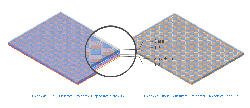
Fig 4a
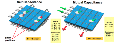
Fig 4b
Projected-capacitance touchscreens, which come in two variations, deliver more accurate location sensing reflective of their more complex construction. An etched single- or dual-perpendicular-layer conductive grid is embedded within a transparent insulator. In mutual capacitance, a touch input changes the mutual capacitive coupling between sequentially scanned row and column electrodes; a capacitor is located at each etched row/column junction. In self-, or absolute-, capacitive-touch technology, conversely, the touch input alters the sensor’s parasitic capacitance to ground.
Self-capacitance systems deliver higher sensed signal strength than mutual-capacitance implementations, but they cannot accurately resolve multiple simultaneous inputs in all cases; two fingers on one grid line deliver the same result as one finger (Fig. 4b). Self-capacitance systems are also prone to “ghosting” errors. Conversely, mutual- capacitance systems sequentially voltage-pulse each row line and subsequently scan column lines for capacitance changes. Mutual-capacitance systems’ touchscreen controllers represent the most complex hardware and algorithm option discussed in this article, but since they individually address each intersection node, the system therefore uniquely senses all touch points. ■
Advertisement
Learn more about Electronic Products Magazine


