Digital control optimizes intermediate-bus efficiency
Digital power converters in power-system represent an enabling technology that allows users to save massive amounts of energy
BY PATRICK LE FÈVRE
Marketing and Communications Director
Ericsson Power Modules
www.ericsson.com
Back in the 1990s, the need for multiple high-current, sub 5-V power supplies to power the silicon that underpins communications infrastructures drove designers to adopt distributed power architectures (DPA). A classic DPA example uses an ac-dc front end to convert utility power to a distribution rail voltage that supplies a number of isolated dc/dc brick converters, each of which supplies a low-voltage load. This model evolved into the intermediate-bus architecture (IBA) that now dominates, where an isolated dc/dc converter downconverts the distribution rail voltage to an intermediate-bus level; in a second stage of downconversion, nonisolated point-of-load converters supply the voltages that the load circuits require.
The dual-stage downconversion IBA approach has several advantages over a single-stage DPA model that notably include saving the cost of providing isolation for each dc/dc converter. The requirement to isolate and downconvert an industry-standard distribution level such as 48 Vdc (and accommodate its 36 to 75 Vdc tolerance) to 3.3 Vdc and below in one step is difficult to accomplish efficiently and accurately when supplying any significant amount of power. The dual-stage IBA approach relieves some design issues as it is now possible to loosely regulate the intermediate-bus voltage to a median level that suits the point-of-load converters that provide tight load regulation.
Analog intermediate-bus converters often use pinstraps to set their outputs at around 12 Vdc to guarantee sufficient headroom for the point-of-load converters under worst-case conditions. This model works well for systems that continuously run close to maximum power, but the advent of dynamic power-conservation techniques that respond to traffic conditions within network infrastructures creates large load swings that impact conversion efficiency. It should be possible to save energy by optimizing the level that the point-of-load converters regulate as load conditions change without compromising the intermediate-bus converter’s performance. This demands programmable power-system components that provide feedback, calling for far greater flexibility than analog converters routinely provide.
Extend efficiency and flexibility
Issues that challenge the best-developed analog isolated dc/dc converter modules include balancing conversion efficiency, regulation performance, and power density. One representative 204-W quarter-brick converter outputs 12 Vdc with ±2% regulation, and 94% typical efficiency at half-load. The 204-W device uses an isolated half-bridge topology with secondary-side voltage control to provide tight regulation, while its stablemate exploits a hard-switched, full-bridge topology with primary-side voltage control that prioritizes output power. The device is configured for best efficiency between about 50% to 70% of full load.
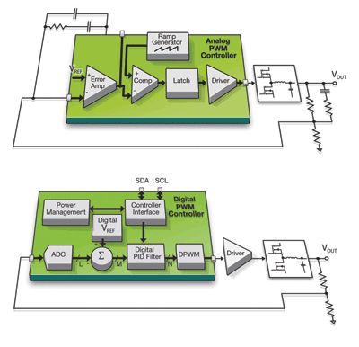
Combining a full-bridge topology with secondary-side control that is difficult to implement within this configuration, the latest-generation product adopts digital inner-loop control to achieve 396 W with ±2% regulation and 96% or better typical efficiency. Relative to its predecessors, this converter’s efficiency curves are flatter and its area of efficient operation extends further into light load conditions. Furthermore, it is programmable and reports operational parameters in real time. Figure 1 compares the core of an analog buck converter with its digitally controlled equivalent:

Fig. 1: Comparison between analog and digital inner-loop control elements
The digital controller substitutes an ADC, numeric reference, adder, and digital filter for the error-amplifier, ramp generator, comparator, and latch that the analog system uses to modulate the PWM stream. As the digital system uses numbers rather than passive-component values to characterize loop responses, it can fine-tune its operation to suit load conditions in real time — optimizing efficiency across a wider area than its best-developed analog counterparts.
Because the digital controller uses a mixed-signal silicon process, a measurement and control subsystem and communications interface come at negligible cost. Adopting PMBus protocols produces a step-change functionality increase over analog converters—a simple four-wire bus and a standard command set allow software to read parameters including voltage, current, and chip temperature in realtime. Software can program parameters on-the-fly that range from an output voltage change to modifying the filter constants that determine the converter’s dynamic performance. Programmable facilities include power-rail sequencing and slew-rate control, warning and fault-condition thresholds, and error recovery responses that—once programmed—operate autonomously. Originally developed for the intermediate-bus converter, similar features appear in a family of digitally-controlled point-of-load converters.
Advanced intermediate bus implementation
The ability to read data from each converter and make adjustments on-the-fly facilitates techniques such as dynamic bus-voltage control, where supervisory software instructs the intermediate-bus converter to lower its output voltage when power demand falls, and to increase it as demand rises. The objective is to minimize the dynamic losses that the point-of-load converters incur without compromising the intermediate-bus converter’s efficiency, saving energy for the system as a whole. But any combination of converters produces complex interactions that are difficult to visualize, making modeling and simulation an attractive approach to developing optimization algorithms. To evaluate the potential of such techniques, engineers at Ericsson Power Modules chose a test set-up that consists of a BMR453 advanced intermediate-bus converter that powers two 20-A BMR450 and four 40-A BMR451 digital point-of-load converters.
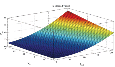
The first step was to acquire some real data to construct a model of each device. Figure 2 plots an example of the power loss results for a BRM450, where the output voltage is 1 Vdc and the load ramps from zero to 20 A while the input bus voltage steps from 4.5 to 14 Vdc.

Fig. 2: Measurement data for the BMR450 20-Amp point-of-load regulator when varying its input voltage from 4.5 to 14 VdcDC and its load current from zero to 20 A.
A least-square-fit methodology was used to construct polynomial models for each device from its test results. Uploading this data to a replica model of the test set-up in the Simulink environment made it possible to visualize the interactions between the power-system components and simulate their responses to varying parameters. It was also possible to evaluate the effects of alternative dynamic bus-control algorithms.
One approach commences by running an algorithm that derives a baseline power loss value. The first control cycle then starts, monitoring relative power loss until reaching a threshold value that triggers an optimization sequence. This complex algorithm performs numerous iterations, but ultimately drives the intermediate-bus voltage to a value that minimizes power loss for the current set of conditions—whereupon the sequence closes. The cycle repeats to minimize power losses within constraints that include trigger-level hysteresis levels and the minimum bus voltage that is necessary to maintain regulation for given load currents.

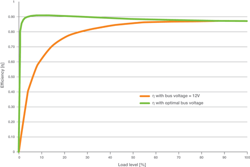
Fig. 3: The improvement in efficiency due to intermediate-bus voltage optimization
Figure 3 models the efficiency improvements that varying the intermediate-bus voltage achieves relative to using a fixed 12 Vdc level for the example test set-up. Importantly, these improvements typically scale with a system’s complexity and power level.
In the context of power-system development, digital power converters represent an enabling technology that allows users to explore power-management scenarios with the potential to save massive amounts of energy—and to do so far more easily than has previously been possible ■
Advertisement
Learn more about Ericsson Power Modules


