Technology evolution: PPTC arc-suppressed connectors
New interconnect technologies can limit potential safety hazards in HVdc applications
BY ROBERT CID
Engineering Manager
TE Circuit Protection
www.circuitprotection.com
The emergence and growth of new high-voltage dc (HVdc) applications – such as electric and hybrid vehicles, photovoltaic systems, and high-density IT server farms and telecom centers – is driving the demand for new connector solutions. Over the last decade, several technologies have been advanced to keep pace with the challenges associated with making and breaking live connections at these higher power levels.
For instance, redundant hot-swappable power supplies for the telephone communications market were developed with traditional connector designs that included sacrificial contact portions and sufficient contact mass to prevent potential catastrophic damage to the equipment. But when the automotive market was poised to move to 42Vdc systems, such traditional means were found to be inadequate. Arcs remained an unavoidable and potentially damaging condition, and a single live disconnect could destroy the connector.
Hot-swap hazards
The telecommunications and networking industries were among the first to implement hot-swap technology in their systems. Hot-swapping refers to the act of inserting or removing an adapter card, plug-in board, or some other device without first removing system power. Many hot-swap applications are very benign, with circuits typically designed to minimize spikes and surges. Connections can be staged with little power on the main, and electronics and relays can be activated to allow power on the main. However, many HVdc applications are susceptible to the formation of arc plasma on live disconnect.
Although safety procedures for making or breaking a live connection on equipment that is connected to hazardous line voltages are established and observed by service personnel, hot-swap interconnection development is focused on minimizing safety hazards and maintaining system reliability.
Attempting to open an inductive circuit often forms an arc between contacts. Inductance in an energized circuit acts as a way to “store” energy. The stored energy is released when the contacts separate and the current temporarily reverses. The subsequent voltage spike created may be much higher than the system voltage.
While lower voltages will not usually jump a gap that is present before the voltage is applied, interrupting an existing current flow often produces a low-voltage spark or arc. As the contacts are separated, a few small points of contact become the last to separate. The current becomes constricted to these small hot spots, causing them to emit electrons. The ionized air and metal vapor form plasma, which temporarily bridges the widening gap. If the power supply and load allow sufficient current to flow, a self-sustaining arc may form. Once formed, an arc may be extended to a significant length before breaking the circuit. In a live disconnect, if the potential difference established between the connecting contacts is great enough the contacts may be damaged.
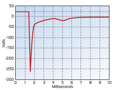
Figure 1 shows the results of a test where a relay was energized at 24Vdc and then disconnected. The voltage spike generated by the coil inductance is -260V, which is the voltage that is actually being disconnected.

Fig. 1: A large voltage spike is produced when contacts are separated in a 24Vdc inductive circuit.
The voltage at the ends of an arc decreases as the current increases. Unintentional arcs in an electrical apparatus can be hazardous because once even a small arc is initiated, if sufficient current is available the arc will grow, and may result in damage to equipment and create a potential fire hazard. The process that can result in a molten connector during a live disconnect is as follows:
• Initial low resistance wiping is followed by decreasing normal force and increasing contact resistance. This results in a molten metal bridge being drawn between the separating contacts. The bridge explosively vaporizes, filling the gap with easily ionized metal vapor.
These actions can damage contact plating and, with sufficient voltage, a conducting plasma can form in the gap which will vaporize any material near it for as long as it lasts. A fast velocity break can help reduce the effects of the arc.
New arc-suppression connector technology
TE Circuit Protection recently developed a new HVdc connector solution that can help mitigate the effects of plasma arcs. In this design the ground contacts engage first for safety. The sacrificial contacts engage next in parallel with power contacts, and the power contacts engage last. The connector housing design also incorporates features that accelerate the mating sequence to quench arcs.

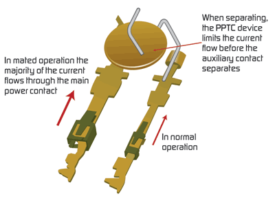
Fig. 2: PPTC device helps limit current in the event of a plasma arc on disconnect.
The connector also incorporates a resettable PPTC device for arc suppression. As a connection is broken it causes a large voltage drop across the connector, which may result in a large plasma arc. As shown in Fig. 2, by placing a PPTC device in parallel with the connector, when the connector is separated current will continue to flow until the PPTC device heats up and goes into a high-impedance state. This limits the current and helps provide a safer disconnect.

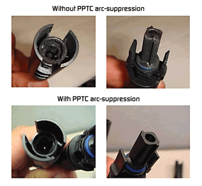
Fig. 3. Plasma arc testing on HVdc connectors with and without arc-suppression.
Figure 3 shows the effects of a plasma arc on two photovoltaic connectors, in a test performed at 550 Vdc, 20 A. The connector which incorporates the PPTC arc-suppression device withstood the test and remained operable, while the connector without the PPTC device was damaged.
How it works
The PPTC circuit protection device is widely used in automotive, portable electronics, multimedia, telecom and datacom applications to help protect equipment from damage caused by overcurrent and overtemperature conditions. PPTC devices are made from a composite of semi-crystalline polymer and conductive particles. At normal temperature, the conductive particles form low-resistance networks in the polymer.
However, if the temperature rises above the device’s switching temperature (TSw) either from high current through the part or from an increase in the ambient temperature, the crystallites in the polymer melt and become amorphous. The increase in volume during melting of the crystalline phase causes separation of the conductive particles and results in a large non-linear increase in the resistance of the device.
The resistance typically increases by three or more orders of magnitude. This increased resistance protects the equipment in the circuit by reducing the amount of current that can flow under the fault condition to a low, steady state level. The device will remain in its latched (high resistance) position until the fault is cleared and power to the circuit is removed – at which time the conductive composite cools and re-crystallizes, restoring the PPTC to a low resistance state and the circuit and the affected equipment to normal operating conditions.
Making and breaking live dc power with electrical connectors and switches is becoming increasingly important in more applications and at higher power levels. The development of new interconnect technologies is focused on limiting potential safety hazards and enhancing the reliability of interconnections in this environment. The resettable PPTC device, in wide use as an overtemperature and overcurrent protection device, has now found use as an arc-suppression element in HVdc connectors. ■
Advertisement
Learn more about TE Circuit Protection Group


