Don’t get your signals crossed
What you need to know about converters (Part 1)
BY TAMARA SCHMITZ
Senior Principal Applications Engineer and Global Technical Training Coordinator
Intersil
www.intersil.com
Despite the benefits of the digital revolution over the past two decades, analog is still alive and very well. We hear more than beeps and we see a spectrum of colors at an array of intensities. As long as humans are involved, analog signals will be of great, sometimes life-saving, importance. Therefore, it is critical to have a conversion device — one that can take in analog signals and transform them into digital ones as well as one that can take in digital signals and convert them into analog ones. Before offering insight into how converters work, it is crucial to understand some of the tradeoffs with analog and digital signals.
First, let’s see what is so great about digital signals. They are simple, easy to store, immune to noise and age and cheap to manipulate. A digital bit contains exactly one piece of information. It can represent on/off, high/low, or one/zero.
As a crude example, think about how many patients a doctor could see each day if all he or she had to do was decide whether or not the patient was injured, not the extent of the injury, just “injured” or “not injured.” Sure, the doctor would be virtually useless in dealing with the human spectrum of emotion and injury, but simplifying the job makes it a whole lot faster.
To continue the analogy, what if a second doctor only saw patients that the first said were “injured”? This second doctor would only have to determine if it was a “major injury” or a “minor injury.” A third doctor could then be called for all of the “major injury” cases to determine if one is “life threatening” or “potentially life threatening.” Eventually, we’d get to the necessary level of specialty like a cardiac surgeon or orthopedist. This would be a digital-conversion modeling of our health system.
Of course, here we are discussing voltage levels instead of human patients. Theoretically, an instant of an analog signal has an infinite amount of information. Usually, it, too, is a level. Instead of just one or zero, an analog signal can be one, zero or anything in between. Let’s say that level is 0.63 V. To make the discussion simpler, full scale (the largest possible value) will be limited to 1 V.

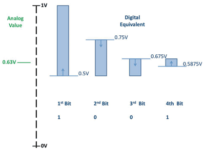
Fig. 1: Process for assigning 4-bit digital representation of an analog input.
Then, how can a digital signal, which is only 1 or 0 ever, represent 0.63 V? Easy: we use multiple bits. The more bits used gives greater resolution.
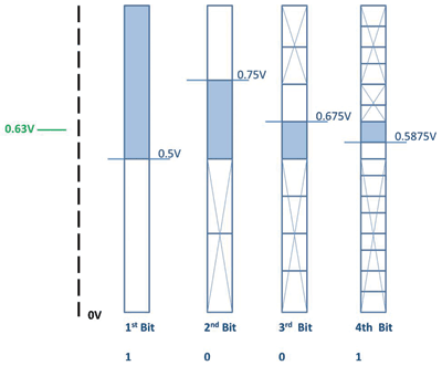
Take a look at Fig. 1 . One bit of information tells us that the value is above 0.5 V, or somewhere in the top half of the range. The second bit takes advantage of the fact that the first bit has eliminated half of the range. (Just like the first doctor sorting which patients are injured from those that aren’t.) The second bit takes the range from 0.5 to 1.0 V and breaks it in half. (Again, like the doctor who separates “major injury” from “minor injury.”) Since the analog value is less than 0.75 V, the second bit shows zero (which would signify “minor injury” in our example above.) This verifies that the analog value is between 0.5 and 0.75 V.
The third bit then identifies whether the analog value is in the upper half or the lower half of this 0.25-V range. Since 0.63 V is closer to 0.5 V, that is the lower half of the range and the third bit is also zero. The fourth bit breaks the 0.5 to 0.675-V range in half again. Since 0.63 V is closer to 0.674 V, the bit is a one. Therefore, the four-bit digital representation of 0.63 V on a 1-V scale is 1001.
It would be natural to be suspicious. The digital signal 1001 represents a range of voltages from 0.5875 to 0.675 V. Don’t we need to be more precise? The answer is maybe.
If you do need to be more precise, then you need to use more bits to represent your analog value. The 4 bits in our example create an error, called a quantization error. If you eventually wanted to convert the digital value back into an analog one, you would probably estimate that value somewhere between 0.5875 and 0.675 V, say the middle value, or 0.63125. That’s an error of 0.00125 V or 1.25 mV.
Is that acceptable? It depends on your system. If you were operating in a medical application where signals were on the order of µV and mV, this would be disastrous. If you had an industrial application where the voltages span 15, 24, or 48 V, then a millivolt or two might be small enough to ignore. As a side note, we conducted our analog to digital conversion with a 1-V full-scale, which may or may not be representative of a conversion in a medical or industrial application.
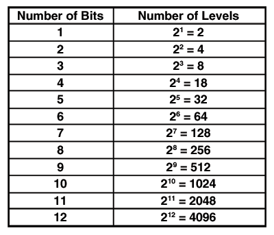
If you did need to be more precise, you would increase the number of bits in your digital conversion. One bit gave you two levels of quantization. Two bits gave four. Three bits gave eight. Four bits gave 16 levels. The pattern is 2n where n is the number of bits. Take a look at Figure 2 . Each new bit divides the previous sections in two — creating twice as many levels!


Fig 2. Number of levels represented at each bit level and the ranges representing the original analog input.
Knowing how many bits are needed is a key to selecting the right converter. Maybe a few examples would help. In 1972, Intel introduced its 8008 microprocessor, which operated on 8 bits. Now microprocessors handle up to 64 bits at blazing fast speeds. A compact disc (CD) stores sound at 16 bits. The human ear can’t decipher higher bit counts. Color displays use 24-bit ranges on their systems, while the analog-to-digital converter in digital cameras usually has 12 or 14 bits.
More digital bits means more resolution to the analog input. Storing an analog signal can be difficult when considering the effects of noise, temperature and voltage fluctuations. Digital signals, as a series of ones and zeroes, virtually eliminate this dependence and allow storage to be very robust. The designer’s next choice is the number of bits. Following that is the speed with which those bits are processed. That will depend on topology and we’ll discuss that next time. ■
Also see “Getting started with converters: The basics of converters and the main performance parameters (Part 2)” http://www2.electronicproducts.com/Getting_started_with_converters-article-facn_intersil_dec2011-html.aspx
Advertisement
Learn more about Intersil


