PPTC devices protect electronic ballasts in fluorescent lamps
PPTC devices can help manufacturers meet the requirements of IEC 61347-2-3, save design/debug time, and conserve space
BY MARK DONG
Sr Application Engineering Manager
TE Circuit Protection
www.circuitprotection.com
Electronic ballasts used in fluorescent lighting systems can experience high failure rates, due to the fact that the ballast manufacturer may not have considered all failure mechanisms or provided appropriate protection against the many different abnormal states that can result from end-of-life (EOL) issues. Although lighting manufactures have come to understand the importance of abnormal-state protection by adding a clause to the international IEC 61347-2-3 standard, many major semiconductor manufacturers provide no, or limited, EOL abnormal-state protection for their devices. In addition, the operation of most ballasts is now achieved through the self-oscillation of a discrete device, the bipolar transistor, which does not provide EOL abnormal-state protection.
This article describes how a polymeric positive temperature coefficient (PPTC) device can help protect electronic ballasts from abnormal-state operations when fluorescent lamps are reaching their EOL. This cost-effective solution simplifies the circuit, thus speeding design time. It also offers space-saving advantages in ballast applications with limited printed circuit board (PCB) space, such as bracket lamps.
Abnormal states of electronic ballasts
The abnormal fault conditions affecting electronic ballasts can be caused by a variety of lamp conditions. These abnormal states are specified below in accordance with the IEC 61347-2-3 standard for ac-supplied electronic ballasts for fluorescent lamps:
1. The lamp or one of the lamps is not inserted.
2. The lamp does not start because one of the cathodes is broken.
3. The lamp does not start although the cathode circuits are intact (deactivated lamp).
4. The lamp operates, but one of the cathodes is deactivated or broken (rectifying effect).
5. A short circuit of the starter switch.
The IEC 61347-2-3 standard stipulates that electronic ballasts should work properly and securely even when the fluorescent tubes are functioning under abnormal or fault conditions. For example, during the start-up phase, if the tube cannot be successfully ignited high current will flow through the resonant circuit and result in high voltage at both terminals of the tube. This high current or high voltage will not only cause damage to the tube’s base, it may also pose a hazard to the operator who is replacing the tube.
The fourth abnormal state mentioned refers to the rectifying effect of fluorescent tubes. A rectifying effect is caused by the frequent inconsistency of the arc current of the lamp in consecutive half-cycles, which is typically a result of damage to the cathode filament or the inability of the emissive material inside the tube to emit electrons. Making the tube diameter thinner can improve the lamp’s light efficiency to some extent, but this can also cause a local rectifying effect in the late stage of the lamp’s life. The rectifying effect will concentrate the high output energy of the electronic ballast on the small cathode of the lamp, which can result in a very high temperature. The increasing temperature of the lamp holder can lead to thermal deformation of the lamp, causing the glass to melt.
This may lead to a tube falling off the fixture or, even more seriously, can result in a thermal event.
Another consideration for ballasts is arcing. Arcing may occur in areas of poor contact, such as inside the tube or between the tube and the lamp. Poor contact can lead to overheating of the tube or the lamp, and can result in the lamp burning.
The IEC 61347-2-3 standard specifies three tests to simulate the effect of the lamp’s end of life: the asymmetric pulse test (Clause 17.2); asymmetric power dissipation test (Clause 17.3); and the open filament test (Clause 17.4). Any one of these three tests can be used to prove the eligibility of the electronic ballast. At the end of the lamp’s life, the standard requires that the ballast shall not make the lamp holder overheat at any voltage between 90% and 110% of the rated supply voltage.
Ballast manufacturers can choose to administer any one of the tests according to the circuit types of the electronic ballast, and testing can be performed using tubes provided by lamp manufacturers. Currently, the protective measures for electronic ballasts are:
• Connect a single-use current fuse to the input of the ac-circuit. Ballast designers may believe that connecting a current fuse at this position will protect the ballast from overcurrent or abnormal states. However, such protection will not be provided under abnormal conditions such as the filament being deactivated. It is often fused after the breakdown of the switching device, which does not provide adequate abnormal state protection.
• Use a protection circuit that incorporates a silicon-controlled rectifier (SCR), bipolar transistor, or other component in the resonant output circuit. This type of electronic circuit protection has the following drawbacks: first it is prone to protection faults and, second, it occupies more PCB space, which is particularly undesirable in small, integrated designs such as bracket lamps or compact fluorescent lamps (CFLs).
• Employ over-power protection to achieve abnormal-state protection. In fact, over-power protection was initially used for arcing protection. Today some manufacturers use this approach for abnormal-state protection. However, it is limited by the rate of arcing detection, which is not appropriate in circuits requiring high-speed arcing detection. Therefore, to some degree, over-power protection cannot effectively prevent overheating of the filaments.
• Connect a resettable PPTC device in the resonant circuit, in series with a resonant capacitor to achieve abnormal state protection. In this case, when the fluorescent tube is in a normal state and the electronic ballast is powered on, the inductor, capacitor, and PPTC thermistor form a series-resonant circuit to make the fluorescent lamp function normally. At this point, the low resistance of the PPTC device will not affect the resonant circuit. If an abnormal state occurs due to deactivation of the filament caused by an aging filament or tube leakage, the PPTC device will activate within seconds. The IEC 62347-2-3 standard stipulates that protection, except for rectifying effect, shall be within 5 seconds, and the rectifying effect protection shall be within 30 seconds. This activation causes the resistance of the PPTC device to exponentially increase, which forces the LC series resonant circuit to stop or increases the frequency to reduce the fault current. This cuts off the high voltage of the resonant network to help protect the ballast, allowing the ballast to begin working again after returning to a normal state. This solution helps provide abnormal state protection, accelerates design time, and conserves valuable PCB space.
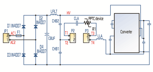
Figure 1 shows a protection scheme using a PPTC device in a T5 14-W electronic ballast with integrated ICs. The PPTC device is connected in the LC series resonant circuit, shown as R1. During normal operation, the resistance of the PPTC is very low and does not affect the normal operating resonant state. If an EOL abnormal state should occur, the current flowing through the resonant circuit will increase to approximately 5 to 6 times the normal operating current.

Fig. 1: Typical circuit using a PPTC device for protection of IC integrated ballasts.
The higher current will then cause the PPTC device to trip and device resistance will increase. As a result, the resonant circuit formed by the PPTC device’s increased resistance will cause the inductor and capacitor to change resonance, and the IC will change the resonant frequency of the ballast.
The increase of the resonant frequency of the ballast will reduce the power of the ballast, thereby reducing the current flowing through the filament and providing the required ballast protection. After the fault has been removed and the power is cycled, the resistance of the PPTC device will return to its original state and the ballast can return to normal operation.
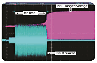
When specifying the resistance of a PPTC device in these applications, the maximum operating temperature and maximum operating current must first be obtained. Next the appropriate PPTC device can be identified by using the temperature derating curve and, finally, it must be determined that the PPTC device complies with the standard for the shortest time required for protection. Figure 2 illustrates the voltage and current chart of a PPTC device during an abnormal state (blue) and after protection (pink).

Fig. 2: Voltage and current of PPTC device during an after abnormal state test.
A PPTC device can also be used in a power input circuit to help provide abnormal-state protection. The efficiency, power factor, and luminous efficacy of electronic ballasts are typically better than those of the electromagnetic ballasts that are widely used in developing countries. Because of these advantages, high-luminous-efficacy tricolor fluorescent lamps using low-power-consumption electronic ballasts are being promoted as green, energy-saving lighting products.
Replacing traditional electromagnetic ballasts and T8 tubes with electronic ballasts and T5 tubes offers significant economic and environmental benefits, and the change is relatively simple to implement. As noted previously, the electromagnetic ballast is connected with an inductor. To make the change to an electronic ballast, the designer can keep the inductor and remove the starter and T8 tube or T12 tube, and then connect the electronic ballast and T5 tube.
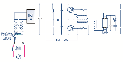
Figure 3 shows how to replace a 36-W T8 tube with a 28-W T5 tube. In this example, the maximum operating current measured is 200 mA, the maximum operating temperature of the ballast is 70°C, and the fault current is approximately 800 mA. The inductive resistance of the electromagnetic ballasts is 48 Ω and, during the short circuit of the rectifier diode, the fault current is 5.5 A.

Fig. 3: PolySwitch device helps provide abnormal state protection where electromagnetic ballast is replaced by an electronic ballast.
It can be assumed that a single-use fuse will be selected for overcurrent protection in this type of design, but selecting the correct device can pose challenges. For instance, while the impact of the surge must be taken into account, if the current value of the fuse is set too high it cannot provide effective protection. Also, when trying to provide for overcurrent protection against an abnormal state, if the current value of the fuse is set too low faults can also occur. A resettable PPTC device is useful in these applications because it is not sensitive to the surge current, yet it can help provide overcurrent protection when an abnormal state does occur.
Using the parameters described above, Fig. 3 shows how a PolySwitch LVR040 device can help provide overcurrent protection for an electronic ballast during an abnormal state in order to meet the necessary protection requirements. Finally, it should be noted that the IEC 61347-2-3 standard requires that abnormal state protection except for a rectifying effect shall activate within five seconds, a very demanding requirement. ■
Advertisement
Learn more about TE Circuit Protection Group


