Choosing potentiometers for position sensing
Obtaining the right potentiometer requires a knowledge of their construction and how their accuracy and linearity is described
BY REINHARD KOCH
Product Manager SENSOFOIL
Hoffmann + Krippner
www.hoffmann-krippner.com
Today, potentiometers dominate the market for linear and rotary path and position sensing. That is not to say that there aren’t other position-measuring systems available on the market (see Table 1 ), and users typically find the best fit to their unique application needs by comparing their features. But for many applications it is potentiometers that provide the best fit.
All potentiometers described here function as part of a voltage divider circuit to provide position information. When integrated into the circuit, a potentiometer will read the voltage in relation to the wiper’s location. With unity signal gain, the potentiometer functions without amplifiers and experiences very low EMI. Evidently, ambient temperature influences do not have an effect, as the voltage signal portrays the relationship between the partial resistances of a voltage divider.
To ensure that the potentiometer will provide a perfect fit, each available construction feature plays a major role. So each feature’s pros and cons should be put side by side and thoroughly compared with regard to such factors as the intended application and its known operating environment.
Material considerations
The resistance material used for potentiometers plays an important role as it makes a difference not only in the sensor’s performance but in its cost as well. The four most commonly found materials are wirewound, carbon, cermets, and conductive ink.
Wirewound consists of a fine coil of resistive wire placed around a varnished copper wire, which is tapped by a wiper. This particular structure produces exceptional linearity; however, it is restricted due to its short life cycle.
Frequently found in trim or low-cost carbon potentiometers is a combination of graphite, carbon, and soot. Again, use of these devices is typically limited by their short life cycles.
Cermets (CERamic + METal) are made up of glass or ceramic material with embedded metal parts. They have average life cycles and are preferably applied in control-panel potentiometers.
Use of conductive inks to form resistive tracks has been highly successful for precision potentiometers. Such devices are known to have long lifecycles.
Construction
Aside from the resistive material, several construction options should be evaluated as well. For one, exposed potentiometers are usually produced using a PCB-base, including a resistive track and tap-line (see Fig. 1 ). Depending on the application requirements, the track will consist of carbon, cermets, or conductive ink as described previously. With this design, it is the responsibility of the user to install the wiper.
Exposed potentiometers are economically priced and very cost effective in high quantities. However, as its name says, the system is entirely exposed. However, one brand of potentiometers, SENSOFOIL, are printed with a polymer coating made up of nano-particles with lotus surface effect. Therefore, dirt particles do not have the ability to accumulate on the exposed conductor path. The design depends on the application, as both linear and rotary variations can be achieved with maximum dimensions of 80 cm in length and 40 cm in diameter. Depending on specifications, the life cycle can be extremely high, with operating temperatures feasible even beyond 125°C.
As oppose to other approaches, this construction technique permits very tight integration; customer specific wiring, including all components, can be installed on the potentiometer’s printed-circuit board. Also a panel shipment is possible. With exposed potentiometers, the wiper is intended for adjustment according to the potentiometer specifications.
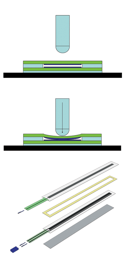
With another type of device, membrane potentiometers, the resistive track (mostly carbon or conductive foil) is printed onto either a solid (FR4) or flexible (foil) base. With these bases, a resistive ink can be chosen according to specific applications. The top foil takes on the tap function as contact is established by means of a non-conductive pressure piece (see Fig. 1). The dimensions tend to be similar to those of exposed potentiometers; however, their compact design has made them a popular solution for restricted installation conditions.

Fig. 1: With a membrane potentiometer, contact is established by means of a non-conductive pressure piece.
Some features of membrane potentiometer construction are:
Foil-based potentiometers (PET-PET) are suitable for applications of 1 to 5 million cycles at a temperature of up to 55°C. Using an adhesive, they can be directly glued on. FR4-based potentiometers (FR4-PET) have the same specifications as PET-PET, however, they can be screwed in (attachment through adhesive optional) and attachment of wires and connectors is less complex.Magnetic membrane potentiometers (PET-MAG or FR4-MAG) provide contact-free operation. A particular iron ribbon is pulled by a magnet and activates the collector foil. This construction presents the advantage of a low hysteresis. High-temperature membrane potentiometers (PET-HYB) are suitable for applications of up to 125°C.
Single- and multi-turn potentiometers are different, as the resistive track is integrated into an enclosure. The connection for the application is established through the use of a shaft. Multi-turn potentiometers are most commonly constructed using wirewound, whereas single-turn potentiometers tend to function on conductive ink.
Also available are linear potentiometers where the FR4 resistive track with conductive ink and wiper is directly integrated into an enclosure. The wiper is moved by means of a push rod. An additional option would be a slide potentiometer, which is designed for manual operation with only a low lifecycle.
Accuracy
While users often require a specific accuracy, varying definitions of the term may result in misunderstandings between the user and the manufacturer of application-specific potentiometers. Quality criteria, including resolution, repeatability, and hysteresis, all factor into determining a potentiometer’s accuracy.
Resolution is primarily determined by the homogeneity, grain-size distribution within the conductive ink layer, wiper contact surface running parallel to the equipotential lines, and the wiper current. By approximation, the resolution in regard to resistive tracks will be indicated as infinitely small.
Repeatability is measured by the arbitrary movement toward a predetermined position, always approaching from the same direction.
The hysteresis value specifies the signal differential resulting when a predetermined position is approached from one side and then again from the opposite side. Hysteresis is mainly affected by mechanical factors such as the bearings, solidity of the wiper system, and the coefficient of friction between the conductive layer and the wiper.
Reproducibility is taken as the arbitrary approach toward a predetermined position from various directions. It represents the sum of 2x resolution + hysteresis.
Linearity
Linearity is repeatedly taken as a feature of quality. The concern is, however, that linearity is often not accurately defined.
Linearity is the maximum deviation to a reference, whereas the type of linearity determines the reference line. The basis of calculation for linearity highly depends on the individual user. Thus, three different concepts exist in the literature: absolute linearity, independent linearity based on BFSL (best fit straight line), and terminal based linearity.
Each of these linearity concepts can be and are frequently used interchangeably; however, the calculations can sometimes vary up to 50%. Hence, it is essential to speak the same “mathematical language” as the user of the potentiometer. Here is the mathematical basis for these terms:
Absolute linearity is based on creating a straight line between the zero voltage point and the maximum voltage supply, at the end of the absolute electrical measurement range. It is expressed by the equation y = mx + b, where b = 0 (no offset).Terminal based linearity : The straight line starts according to the defined lower measurement range (intercept at lower 10% margin and measurement curve) and ends with the defined upper measurement range (intercept at upper 10% margin and measurement curve). The margins depend on the type of the potentiometer and manufacturer, and for the equation y = mx + b, b ≠ 0.BFSL : The straight line according to the best-fit-straight-line-method is placed within the device’s actual measuring range for the maximum deviations to be minimized as they are equal in both positive and negative directions.
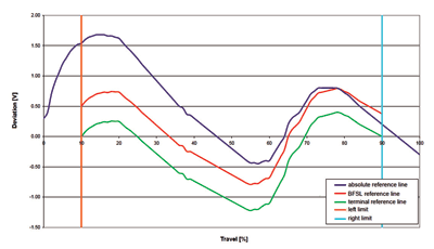
The differences are clearly evident in Fig. 2 . This example shows that end results differ when measurements are taken from the same object, but calculations are based on different methods of determining linearity. The absolute linearity (upper curve) gives an error of 1.7% , the BFSL-method (middle curve) measures a value of 0.8%, and the terminal based linearity (bottom curve) shows an error of 1.3%.

Fig. 2: Applying different means of determining linearity to the same measurement data show how critical the method can be.
Calculation of linearity gets more complex: the user must consider the section of the potentiometer being measured. This explains how, using the same method for measurement, an unequal part of the effective resistance track gets cut off, because the nonlinearity on both ends increases due to the application method of the resistance. Using a 100-mm linear potentiometer as a reference, the red line in Fig. 3 displays the measurement range of 10% to 90% with a result of 0.5% nonlinearity; the blue line measures the 20% – 80% range with a nonlinearity of 0.25%.

Fig. 3: Referencing to a 100-mm linear potentiometer, nonlinearity at 60% path is 0.25%, at 80% path is 0.50%.
With a thorough comprehension of application needs and specifications, clear communication, and an understanding of which parameters are indispensable, the most effective system can be achieved. ■
| Sensor type | Operating temperatures | Response time | Comment |
| Capacitive | −40° to 80°C | 0.1 to 1 ms | Suited for fast precise movements |
| Hall effect | −40° to 125°C | 1 to 10 ms | Low EMC-sensitivity at dc volatages |
| Inductive | −40° to 80°C | 1 to 10 ms | Very high (µm) resolution |
| Magnetoresistive | −40° to 125°C | 1 to 10 ms | Competes with Hall Effect devices, but temp. coefficients problematic |
| Magnetostrictive | 0° to 125°C | 1 to 10 ms | Well-suited for sturdy linear measurements from 30 cm and above |
| Membrane poetentiometer | −40° to 125°C | Real time | Like potentiometer, but for restricted installation space |
| Optical | −20° to 80°C | 10 to 100 µs | Very good measurement speed |
| Potentiometer | −40° to 125°C | Real time | Dominant technology today |
| Ultrasonic | 0° to 50°C | 100 ms | Suited for linear and distance measurement under static conditions |
Advertisement
Learn more about Hoffmann + Krippner


