Magnetometer basics for mobile phone applications
Used in advanced measurement gear for years, magnetometer technology must be reevaluated for consumer devices
BY YONGYAO CAI, YANG ZHAO, XIANFENG DING, and JAMES FENNELLY
MEMSIC
www.memsic.com
Use of magnetic sensors is rapidly expanding, driven by user demands in automotive, industrial, military/aerospace and consumer applications. Initially, magnetic sensors were developed and used almost exclusively for navigation and tracking purposes, mostly in the military/aerospace and industrial arenas. In the last couple of years, consumer electronics applications like smart and mobile phones, computer tablets, gaming and audio/video devices, desktop PCs and personal electronics have emerged for magnetic sensors, enabled by advances in microelectromechanical system (MEMS) technology as well as silicon IC processing advances.
One of the newest consumer applications is magnetometers for mobile phones, also known as e-compasses. Some call these e-compasses gaussmeters which generally measure magnetic fields greater than 1 nT.
Several magnetic sensing approaches are being used by a number of companies for consumer mobile phones, but there are essentially four methods, each with its own pros and cons. These include Hall effect, giant magnetoresistance (GMR), magnetic tunneling junction (MTJ) sensing, and anisotropic magnetoresistance (AMR). A fifth, Lorentz force, has just appeared.
A key factor in selecting the right type of sensor is cost. Some manufacturers foresee costs for their chips at less than a dollar for consumer electronic items like mobile phones.
Another crucial parameter is sensitivity. Designing a magnetometer with a wider bandwidth can alleviate noise sensitivity levels. However, cost and sensitivity are interrelated. Sensitivity can be improved by the use of additional electronic signal-processing circuitry as well as software algorithms, but this involves a trade-off with costs, size, and power, all of which are critical for mobile phones. Thus such trade-offs must be made very carefully.
Other important considerations which can affect end-user costs are layout architecture, packaging, and testing. Some magnetometers make use of a separate 2- or 3-axis accelerometer chip, combined with a magnetic sensor chip, both of which are housed in a larger package. Other magnetometers are single-chip devices that provide both accelerometer and magnetic sensing functions in one package.
A closer look at the most common magnetometer sensing techniques will give a better understanding of their pros and cons.
Hall effect
The most common magnetometer method is the Hall effect method. It works on the principle that a voltage can be detected across a thin metallic element, when the element is placed in a strong magnetic field perpendicular to the element’s plane (Fig. 1 ). The detected voltage is referred to as the Hall voltage.
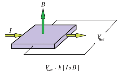
Fig. 1: The Hall Effect principle works by detecting a voltage across a metallic surface (the Hall voltage) in response to a magnetic field that’s perpendicular to the metallic surface.
The Hall-effect method has some drawbacks. Compared to other methods, it produces a smaller output signal and has comparatively low sensitivity and temperature stability. But it is relatively small in size, dissipates little power, and is low cost.
A Hall effect magnetometer’s sensitivity can be increased with a magnetic-flux concentrator, but this increases the overall footprint of the sensor. The concentrator also introduces potential nonlinearity and hysteresis effects, and reduces usable magnetic field range.
GMR
The GMR effect discovered in the late 1980s is actually a quantum effect. GMR sensors utilize the quantum nature of electrons that have two spin states, up and down. Conducting electrons with spin direction parallel to the sensor film’s magnetic orientation move easily and thus produce low electrical resistance.
In its simplest form, GMR is achieved by using four-layer structure that consists of two thin-film ferromagnets separated by a conductor. The fourth layer is an antiferromagnetic field that is used to pin or inhibit the rotation of the magnetization of the ferromagnetic layers. This structure is essentially a spin valve (Fig. 2 ).
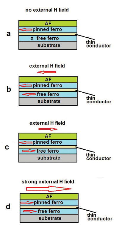
Fig. 2: In a GMR spin valve, when H = 0, the magnetization of the free ferromagnetic layer is perpendicular to the magnetization of the pinned ferromagnet and R = R(0) (a). When H is parallel to the magnetization of the pinned ferromagnet, a low-resistant state results and R
GMR magnetometer sensors exhibit high sensitivity levels, produce large signals, are highly temperature-stable, and are physically small in size. They’re also said to be low in power dissipation.
The matter of comparative cost is a debatable one. Historically, GMR magnetometers have involved complex structures that are difficult to fabricate and are thus higher in cost to manufacture. However, some recent work on this principle has claimed that low-cost processing is possible compared to other magnetometer methods.
MTJ
A third competitive approach is based on the magnetic tunneling junction (MTJ) principle discovered in the mid 1990s, which makes use of MTJs’ tunnel magnetoresistance, a quantum mechanical phenomenon. An MTJ structure consists of two ferromagnets separated by a thin insulator. If the insulating layer is thin enough (typically a few nanometers), electrons can tunnel from one ferromagnet into the other.
The device includes two electric contacts, two magnetic layers and one barrier layer (Fig. 3 ). The tunneling current is controlled by the relative orientation of the magnetic fields in the free and pinned magnetic layers. The current is maximized when the fields in both layers are aligned with one another. It is minimized when the two fields have opposite polarity. Essentially, the MTJ acts as a resistor which is dependent upon the magnetic field.
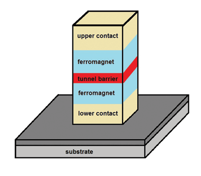
Fig. 3: A magnetic tunneling junction (MTJ) magnetometer consists of two ferromagnets separated by a tunnel barrier, which is an insulator layer thin enough to allow electrons to tunnel from one ferromagnet to the other.
The MTJ method can produce a large signal with high sensitivity and low noise. But MTJ-based devices have a narrow bandwidth (± 1,000 µT), consume too much power, and are priced too high for most mobile devices.
AMR
Anisotropic magnetoresistance (AMR) is another approach that was introduced a few years ago. This concept makes use of a common material, permalloy, to act as a magnetometer. Permalloy is an alloy containing roughly 80% nickel and 20% iron. The alloy’s resistance depends on the angle between the metallization and the direction of current flow. In a magnetic field, magnetization rotates toward the direction of the magnetic field and the rotation angle depends on the external field’s magnitude.
Permalloy’s resistance decreases as the direction of magnetization rotates away from the direction in which current flows, and is lowest when the magnetization is perpendicular to the direction of current flow. The resistance changes roughly as the square of the cosine of the angle between the metallization and the direction of current flow.
Permalloy is deposited on a silicon wafer and patterned as a resistive strip. The film’s properties cause it to change resistance by 2% to 3% in the presence of a magnetic field. In a typical configuration, four of these resistors are connected in a Wheatstone bridge configuration to permit the measurement of the magnitude of the magnetic field along the direction of the axis (Fig. 4, top ). The bandwidth is usually in the range of 1 to 5 MHz.
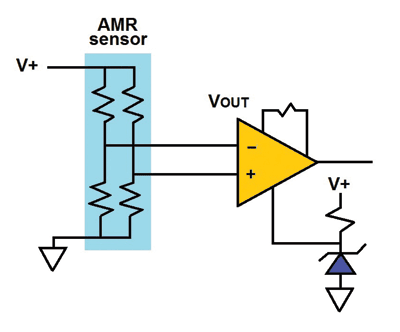
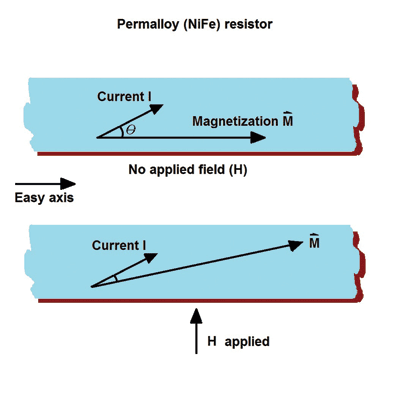
Fig. 4. The basic AMR sensor circuit (top) uses a permalloy thin film whose magnetization vector, M, is influenced by the magnetic field to be measured. As the angle between the vector M and a current flowing though the tfilm (bottom) changes due to the applied field, the film’s resistance changes.
AMR properties are well behaved only when the film’s magnetic domains are aligned in the same direction. This configuration ensures high sensitivity and good repeatability with minimal hysteresis. During fabrication, the film is deposited in a strong magnetic field that sets the preferred orientation, or “easy” axis, of the magnetization vector M in the Permalloy resistors (Fig. 4, bottom ). The M vector is set parallel to the length of the resistor and can be set to point in either direction, left or right, in the film.
Although the AMR principle supplies a lower output signal level than other competitive approaches, the level is more than enough for consumer mobile phones. Recent developments in AMR technology have made AMR even more competitive with the Hall effect. AMR also has better sensitivity than other methods and reasonably good temperature stability.
Lorentz force
The most recent arrival on the low-cost-magnetometer scene is Lorentz force magnetometers MEMS devices that detect the motion of a miniature bar magnet. The fact that these magnetometers can be manufactured on the same wafer holding MEMS and CMOS circuitry could mean that devices based on this method can be made at low cost, but this remains to be seen. The Lorentz force sensor’s magnetic field resolution is limited by electronic noise from the detection electronics, and its structure’s relatively high natural frequencies make it less sensitive to acceleration. ■
Advertisement
Learn more about MEMSIC


