Challenges of testing MSR base-station transmitters
Wider-bandwidth multi-standard radio (MSR) requires support not only of multiple carriers but also multiple formats
BY MOTO ITAGAKI
Senior Application Product Planner
Agilent Technologies
www.agilent.com
Next-generation base-station transmitters and receivers will support wider bandwidths and include not only multiple carriers (MCs) of a single radio format, but also multiple formats in one transmitter path. For example, GSM, W-CDMA and LTE MCs can now be simultaneously transmitted from a single Multi-Standard Radio (MSR) base-station unit.
The ability to support multiple formats in a cellular network is critical to driving down the size and cost of base stations. Thus MSR base stations are expected to enable a smooth and seamless migration from the currently deployed 2/3G radio formats toward 3.9G (for example, LTE) and even 4G (such as LTE-Advanced) technologies.
While this will clearly benefit network operators, service providers, and consumers alike, adoption of MSR MC configurations comes at a price — namely, having to deal with testing MSR base-station transmitters. Finding a quick, effective way to perform measurements is essential to ensuring successful deployment of MSR base stations.
New requirements
Release 9 of the 3GPP specification includes a series of documents (3GPP TS37 Rel-9) that focus on MSR and in particular, on base-station conformance testing when multiple radio access technologies are supported. These documents cover the MSR MC combinations of 3GPP frequency-division duplex (FDD) formats (e.g., LTE FDD, W-CDMA/HSPA and GSM/EDGE) and 3GPP time-division duplex (TDD) formats (e.g., LTE TDD and TD-SCDMA). In contrast to receiver conformance testing requirements, which are similar to those of each single format, transmitter conformance tests must be performed under MSR MC allocating scenarios.
The RF requirements defined in the TS37 documents specify measurement of channel power, modulation quality in terms of error vector magnitude (EVM), frequency error (with the same calculation process as for EVM), spurious emissions, and operating band unwanted emissions or spectrum emissions mask (SEM), when testing MSR MC-active configurations.
Measurement of ACLR, occupied bandwidth (OBW), and time alignment between transmitter branches is required when testing each single-format single carrier. While these three measurements are not required to test under the MSR MC-active configuration, some base-station manufacturers may want to test them under this configuration anyway. Testing under this configuration more closely resembles a realistic use scenario and provides test efficiency for covering all available formats that the base-station-under-test supports.
Spectrum measurements
Much like single-format test cases, spectrum measurements for MSRs can be performed using either swept analysis (in a signal or spectrum analyzer), or fast Fourier transform (FFT) analysis (in a vector signal analyzer). However, for out-of-band or out-of-channel measurements such as spurious emissions, ACLR, and SEM, swept analysis is generally more appropriate, since the frequency spans are typically much wider than those for measurement of a single carrier.
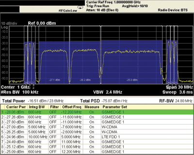
In an example swept-spectrum view of a carrier-channel power measurement for the MSR conformance testing defined in 3GPP TS37.141 (see Fig. 1 ), a dedicated MSR measurement application (swept SA-based MSR channel power measurement) was used for simplicity. The test signal includes a total of six GMSK/8PSK MCs (with three each at the lowermost and uppermost frequency offsets in the RF bandwidth), two W-CDMA carriers, and one LTE FDD 10-MHz carrier.

Fig. 1: In this multi-carrier channel power measurement, taken using an Agilent N9083A MSR measurement application running on an X-Series signal analyzer, the MSR signal-under-test is an example of 3GPP Test Configuration 4c (TC4c), with an assumed RF bandwidth of 25 MHz for the base-station transmitter.
Alternatively, the measurement can be made by manually configuring a swept SA with an appropriate resolution bandwidth (e.g., 100 kHz) that is narrow enough to distinguish GSM carriers and add integrated band power markers for each carrier-of-interest
Digital modulation quality
When evaluating signal modulation qualities such as the EVM of each carrier under MSR MC-active configuration, a key consideration for the test engineer is how to acquire all available active carriers at once throughout the wide bandwidth that the MSR base station’s RF port supports. Recall that there is no mandatory requirement that all active carriers be simultaneously captured using an analyzer with a wide-band acquisition front-end.
For transmitter conformance testing, measurements are made with an arbitrary repetitive-patterned waveform from the device-under-test, such as Test Models (TMs). The 3GPP TS37.141 MSR base station conformance test specification defines several MSR MC allocating patterns for testing called Test Configurations (TCs). Therefore, even without having wide-band front-end hardware to capture all available MSR MCs simultaneously, transmitter conformance testing can be performed using a conventional signal acquisition approach.
To do so, the test engineer essentially captures each single carrier and makes modulation quality measurements one-by-one, sequentially, with a narrow acquisition input bandwidth front-end just wide enough to capture each single carrier. Next, the engineer switches the frequency to the next carrier, captures and measures EVM, and so on. Because this approach does not require expensive wide-band front-end hardware to cover all carriers at once, or large-size waveform samples for computing EVMs after wide-band signal capturing, it is deemed simpler and more cost-effective.
The current widest cellular carrier bandwidth is LTE’s 20-MHz bandwidth, but what about LTE-Advanced, which, according to LTE Rel-10, will allow up to a 100-MHz system bandwidth? Because it is designed to support carrier aggregation, each component carrier can be up to 20-MHz wide. Added time and effort would therefore be required to switch each carrier measurement one after another, although how much time and effort exactly will depend on how the sequential capture and demodulation calculation process/algorithm is designed in the tester/analyzer equipment or the external control program. If “fast LO and mode switching among each carrier” is applicable, the throughput disadvantage becomes rather small.
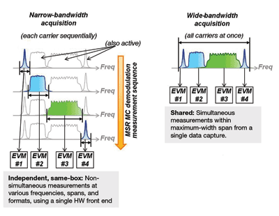
While the cost of using wide-bandwidth analyzer hardware to simultaneously capture all active MCs of interest may be more than that of narrow-bandwidth hardware, it is still a worthwhile expenditure when verifying and troubleshooting instantaneous events happening in MSR radio devices, such as for functional design validation and real system operating tests (see Fig. 2 ). Here, EVM measurement of each carrier is made separately by taking out each carrier from the acquired wide-band waveform. The captured sample includes all active carriers that are truly simultaneous events with one other.

Fig. 2: This image compares the use of sequential acquisition of each carrier using narrow bandwidth hardware on the left with the use of simultaneous acquisition of all carriers using wide bandwidth hardware on the right, for modulation analysis.
Regardless of whether the wide bandwidth or narrow bandwidth analyzer hardware approach is employed, each requires the use of an appropriate receiver filter for each carrier-of-interest. The filter rejects adjacent carrier power interference so that the analyzer can achieve good enough synchronization and the demodulation robustness necessary for each carrier-of-interest under the MC-active condition.
In the case of W-CDMA (or the TDD format TD-SCDMA) carriers, the standard specification clearly defines the receiver filter shape as a 3.84 MHz (1.28 MHz for TD-SCDMA) Route Raised Cosine filter with a roll-off factor of 0.22. For formats like GMSK and LTE, no such clear specification exists. Instead, an adjacent carrier-rejection filter may need to be added to the analyzer that has an appropriately steep roll-off factor, even if it means sacrificing some modulation quality.
Clear choices
So when making spectrum and power measurements of MSR MC base-station transmitter devices, the swept-SA measurement approach is still appropriate. It can be used in much the same way as when measuring single-carrier transmitter devices.
When analyzing the modulation quality of each carrier under MSR MC configurations, two different approaches can be employed. With the first approach, each carrier is acquired sequentially with a narrow bandwidth hardware front-end. This approach is both straightforward and cost effective, assuming that the MSR signal-under-test is an arbitrary, repetitive test-mode signal.
With the second approach, all carriers are simultaneously acquired with a wide bandwidth hardware front-end. This approach enables truly simultaneous capture of all carriers for troubleshooting instantaneous events. The downside is that the SA hardware can be expensive. The total throughput between each approach depends on how the test sequence algorithm is designed or programmed. ■
Advertisement
Learn more about Keysight Technologies, Inc.


