New automotive designs need buck-boost converters
The capability of new power ICs to continually deliver a well-regulated output, regardless of wide input voltage swings, has created new challenges for power management ICs
BY JEFF GRUETTER
Product Marketing Engineer
Linear Technology
www.linear.com
Every year automobiles incorporate increasingly complex electronic systems to maximize comfort, safety and performance while simultaneously minimizing harmful emissions. According to market researcher Databeans, automotive semiconductors are expected to grow at a CAGR of 9% from 2011 to 2014. Increasing electronic content in cars is driven by new safety systems, infotainment systems (telematics), engine and drive train management, satellite radio and TV, LED lighting, Bluetooth and other wireless systems, and rear-view cameras. Five years ago, these systems were found only in high-end European luxury cars, but now they are now being integrated into midrange automobiles from every manufacturer, accelerating automotive IC growth at an even faster rate.
A key driver for electronics systems is the adoption of new engine and drive-train designs, which include direct injection, stop-start controls, and various levels of hybrid/EV configurations. At the same time, worldwide emissions standards are becoming stricter while pressure to increase gas mileage continues. Yet customers are demanding even higher performance. Once mutually exclusive requirements, the adoption of smart engine control systems, a myriad of sensors, and several DSPs enable car manufacturers to attain higher levels of engine efficiency with cleaner running engines.
Electronic control units (ECUs) are quickly proliferating to optimize many aspects of automotive designs, ranging from engine and drive train management to dynamic chassis control. Collectively, these new systems improve safety, performance, and comfort for the driver and help provide a cleaner environment for all of us.
As the electronic component count in automotive systems increases, the available space requirements continue to shrink, greatly increasing the density of each system. All of these systems require power conversion ICs, usually with multiple voltage rails for each subsystem. Traditionally, linear regulators provided the majority of these power conversion needs as efficiency and small size were not of primary importance. But as the power density has increased by orders of magnitude, and many applications require relatively high ambient-temperature operation, any practical heat sinking is too large to be accommodated.
Thus, power conversion efficiency has become critical, driving step-down switching regulators to replace linear regulators. However, emerging automotive designs require the switching regulator to deliver a constant output voltage regardless if the input is above, below or equal to the output. The capability of new power ICs to continually deliver a well-regulated output, regardless of wide input voltage swings, has created new challenges for power management ICs. Not only must they offer a robust design, but they must also offer the highest efficiency, lowest quiescent current, and compact solution footprints.
Electronic transient challenges
In order to maximize fuel mileage while minimizing carbon emissions, alternative drive technologies are continuing to evolve. Whether these new technologies incorporate an electric hybrid, clean diesel or a more conventional combustion design, chances are they will also incorporate a stop-start motor design. Already prevalent in virtually all hybrid designs across the world, many European and Asian and car manufacturers have also been incorporating this design into conventional gas and diesel vehicles as well. In the USA, Ford recently announced that it will incorporate stop-start into many of its 2012 domestic models.
The concept of a stop-start engine is straightforward, the engine is shut off when the vehicle comes to a stop, and restarted immediately before the vehicle accelerates. This eliminates the fuel used and emissions generated while the car is stopped in traffic or at a stop light. This stop-start design can reduce fuel consumption and emissions from 5% up to 10%. However, the biggest challenges to these designs, is making the entire stop-start scenario imperceptible to the driver.
There are two major design hurdles to make the stop-start capability invisible to the driver. The first is a quick restart time, by using an enhanced starter design, some manufacturers have reduced the restart time to under 0.5 s, making it truly invisible. The second design challenge is to keep all of the electronics, including air conditioning powered directly from the battery while the engine is turned off, and still maintaining enough reserve to quickly restart the engine when it’s time to accelerate.
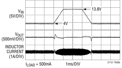
In order to incorporate the stop-start feature, the drive train does require a modified design. Namely, what was once the alternator may also double as an enhanced motor starter to ensure a quick re-start. Additionally stop-start electronic control unit (ECU) must be added to control when and how the engine starts and stops. The battery must be capable of powering the vehicle’s lights, environmental control and other electronics, while the engine/alternator is off. In addition, it must be capable of powering the starter when the engine is once again needed. This extreme loading of the battery introduces yet another design challenge, this time electrical, as the large draw of current required to restart the engine can temporarily pull the battery voltage as low as 4 V, quite similar to the voltage profile in Fig. 1 . The challenge for electronics arises in supplying a well regulated 5 V (or higher) when the battery bus voltage is briefly below the required output voltage, then returns to a nominal 13.8 V when the charger returns to steady state.

Fig. 1: Stop-start and cold-crank line transient.
Cold crank is a condition that occurs when a car’s engine is subjected to cold or freezing temperatures for a period of time. The engine oil becomes extremely viscous and requires the starter motor to deliver more torque, which in turn, draws more current from the battery. This large current load can pull the battery/primary bus voltage below 4.0 V upon ignition, after which it typically returns to a nominal 13.8 V. The electrical result to the vehicles power bus looks very similar to a stop-start scenario seen in Fig. 1, but for very different reasons. It is imperative for some applications such as engine control, safety, and navigation systems to require a well regulated output voltage (usually 5 V) through a cold-crank scenario, so as to continually operate while the vehicle starts.
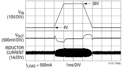
Load dump (see Fig. 2 ) is a condition where the battery cables are disconnected while the alternator is still charging the battery. This can occur when a battery cable is loose while the car is operating, or when a battery cable breaks while the car is running. Such an abrupt disconnection of the battery cable can produce transient voltage spikes up to 60 V as the alternator is attempting a full-charge of an absent battery. Transorbs on the alternator usually clamp the bus voltage somewhere between 30 and 34 V and absorb the majority of the surge. However, dc/dc converters downstream of the alternator are subjected to transient voltage spikes as high as 36 V. These converters are not only expected to survive, but must also continually regulate an output voltage through this transient event.

Fig. 2: 36-V load-dump-condition line transient.
Always-on systems need ultralow supply current
Many electronic subsystems are required to operate in standby or keep-alive mode, drawing minimal quiescent current at a regulated voltage while in this state. These circuits can be found in most navigation, safety, security, and engine management electronic power systems. Each of these subsystems can use several microprocessors and microcontrollers.
Most luxury cars have over 100 of these DSPs onboard and 10% to 20% of these will operate in two different modes. First, when the car is running the power supplies that power these DSPs will generally operate at full current fed by the battery and charging system.
However, when the car ignition is turned off, the microprocessors in these systems must remain alive, requiring their power ICs to provide a constant voltage while drawing minimal current from the battery. Since there can be upward of 20 of these always-on processors operating at once, there is an significant power demand on the battery even when the ignition is turned off.
Collectively, hundreds of milliamperes of supply current can be required to power these always-on processors, which could completely drain a battery in a matter of days. For example, if a car’s high voltage step-down converters require 2 to 10 mA of supply current each, combining 20 of these from security systems, GPS systems, and remote keyless entry systems with other mandatory always-on systems such as ABS brakes and leakage current from electronically actuated windows, could drain a battery after an extended 3-week business trip, rendering it unable to crank the engine.
Quiescent current of these power supplies needs to be drastically reduced in order to preserve battery life without increasing the size or complexity of the electronic systems. Until recently, the requirement of high input voltage capability and low quiescent currents were mutually exclusive parameters for a dc/dc converter IC.
In order to better manage these requirements, several automotive manufacturers created a low-quiescent-current target of 50 µA for each always-on dc/dc converter. Until recently, systems manufacturers were required to connect a low quiescent current, LDO in parallel with a step-down converter, and switch from this converter to a much-lower-current LDO each time the car was turned off. This created expensive, bulky, and relatively inefficient solutions.
Solutions
As demonstrated, the voltage of an automotive battery bus can vary quite a bit as it is exposed to different scenarios. It appears that with the universal adoption of stop-start and automotive ECUs, as well as other electronics must operate seamlessly even when the bus voltage dips below the required output voltage.
Once the domain of step-down or buck regulators, new applications require automotive power ICs to also offer a boost function when the bus voltage drops below the required output. For example, what happens if an ECU requires a 5-V rail and must operate through cold-crank, stop-start conditions, and load dump?
When the input voltage is below 5 V in a cold-crank or start-stop scenario, it must act as a boost converter delivering a fixed 5 V, yet as the input rises to 13.8 V as the alternator kicks in, it must act as a buck converter. Similarly during a load dump scenario, it must also continually deliver 5 V, even if the input rises to 36 V. Additionally, the transition from boost to pass through to buck converter must be completely seamless as the ECU requires an uninterrupted and well regulated 5 V.
The LTC3115-1 synchronous buck-boost converter delivers up to 2-A continuous output current from a wide range of power sources such as single-cell, Li-ion to 24-V/28-V industrial rails to 40 V automotive inputs. Its 2.7 to 40-V input and output range makes it ideal for automotive systems.
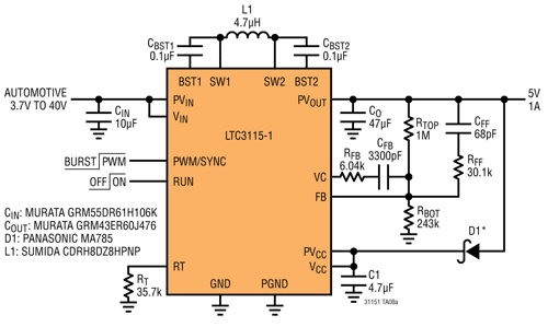
As can be seen in Fig. 3 , it requires only a single inductor and minimal externals. Its ability to provide a well regulated output with inputs above, below or equal to the regulated output makes it ideal for automotive applications which require a well regulated output in spite of wide input voltage variations.
The low-noise buck-boost topology incorporated in the LTC3115-1 provides a continuous, jitter-free transition between buck and boost modes, optimizing it for noise-sensitive applications. The LTC3115-1’s switching frequency is user programmable between 100 kHz and 2 MHz, and can be synchronized to an external clock. Proprietary third-generation buck-boost PWM circuitry ensures low noise and high efficiency while minimizing the size of external components. The combination of tiny externals and a 4 x 5-mm DFN or TSSOP-20E package provides a compact solution footprint.

Fig. 3: LTC3115-1 typical automotive schematic.
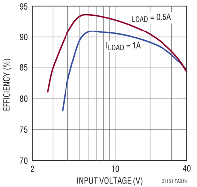
The LTC3115-1 incorporates four internal low-RDS(on) n-channel MOSFETs to deliver efficiencies of up to 94% in typical automotive applications (see Fig. 4 ). User-selectable burst-mode operation lowers quiescent current to only 50 µA, improving light load efficiency and extending battery run time for always-on systems. For noise-sensitive applications, burst-mode operation can be disabled. Additional features include internal soft-start, programmable undervoltage protection, short-circuit protection, and output disconnect.

Fig. 4: LTC3115-1 efficiency graph of typical automotive schematic.
The rapid growth of very specialized electronic subsystems in automobiles has created stringent performance requirements for power ICs in automotive applications. Depending on where the power supplies operate on the automotive power bus, they may be subjected to stop-start, cold-crank, and load-dump conditions and must be capable accurately regulating an output voltage regardless whether the input is below, above or equal to the required output. Additionally, some of these systems will operate in an “always-on” standby mode requiring minimal supply current. As more electronic systems are added to each vehicle, minimizing the solution footprint while maximizing efficiency is also critical. Fortunately some power IC designers have created solutions to meet these requirements, paving the way for even higher electronic content in future cars. ■
Advertisement
Learn more about Linear Technology


