Low-cost CCR charging for rechargeable batteries
A constant current regulator can create a low-power, low-cost, high-efficiency charging solution for rechargeable batteries
BY STEVE SHEARD
Strategic Programs Manager
ON Semiconductor
www.onsemi.com
This article looks at how a constant current regulator (CCR) can be used to create a low-power, low-cost, high-efficiency charging solution that is suitable for rechargeable batteries for a broad selection of applications. A charger has to fulfill the basic roles of charging the battery, optimizing the rate at which the charging process is carried out, then terminating this process. By implementing a simple controller mechanism it is possible to terminate charging in a timely manner.
Chargers can use either constant dc or pulsed-dc power approaches. For each of these, the output does not change, but remains at a constant level throughout the charging period and is not affected by the total charge that has already been placed upon the battery. Alternatively, for small capacity batteries, such as those generally used in portable applications, trickle chargers are often called for. Here the battery is charged at close to its self-discharging rate, thus maintaining a full capacity battery. In this particular situation a battery regulator of some form is recommended, to avoid overcharging (as otherwise it will continue to charge the battery even when it is fully charged), which could potentially shorten the battery’s life.
The capacity of the battery over a 1 hour period is denoted by C. In order to explain this a little further, take a battery rated at 800 µAh. If this was to be charged at 0.5 C, a charge current of 400 µA over a period of two hours would be required.
As well as the C value, the charge current needed for a rechargeable battery will depend on the technology the battery is based upon. Each of the technologies currently used has attributes that make them more suitable for certain kinds of applications. The three most common rechargeable battery technologies are:
1. Nickel metal hydride (NiMH): Has a very high storage capacity compared to other technologies, allowing greater levels of charge in smaller form factor batteries.
2.Nickel cadmium (NiCd): Has a longer lifespan than NiMH and exhibits a lower self-discharge level. NiCad also allows production of batteries that have the lowest cost of the three technology options.
3.LIthium-ion (Li-ion): Results in lightweight batteries that are capable of working at lower temperatures, making them particular suited to outdoor application scenarios. This technology requires charging times that are comparatively short. Furthermore, it can cope with a greater number of charging cycles than NiCad or NiMH alternatives.
Simple charging solution
A simplified illustration of a typical charging circuit is shown in Fig. 1 . It consists of a voltage reference, power source, LED indicator, controller, and CCR. For a NiMH battery the nominal voltage is 1.2 V/cell and should be charged up to 1.5 V to 1.6 V/cell. There are several different techniques for determining when to terminate the charge. These include peak voltage detection, negative delta voltage, delta temperature (dT/dt), temperature threshold and timers. For high end chargers these may be all combined together. For a CCR charger, a peak voltage detecting circuit is employed – which terminates the charging process when a predetermined peak voltage has been reached. This peak is 1.5V/cell and will allow charging of the battery to approximately 97% of full capacity. As they behave in a very similar way, NiCad batteries can be charged using the same methodology. The charging cycle of Li-ion batteries is more complicated. Here the usual method is to charge the battery to 4.2 V/cell at between 0.5- and 1-C charging capacity followed by a trickle charge. The temperature rise of Li-ion batteries should be kept below the 5°C mark while the charging process is being carried out a higher temperature rise will indicate potential for combustion. It is during the trickle charge part of the charging cycle that the battery temperature will rise by the greatest degree and is therefore when the risk of combustion occurring is at its highest. Often some form of smart IC will be employed to monitor and control the charge of the battery and thereby safeguard against this.
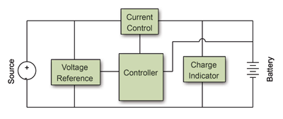
Fig. 1: Block diagram of typical charging circuit.
Simple charging circuit
We will first discuss the different parts of the charging circuit.
In Fig. 2 the setting of the reference voltage (Vref) is shown utilizing a three-terminal programmable shunt regulator. The resistor R2 is set to 1.0 kΩ and Rref can then be adjusted to match the Vref required. The equation that describes the ratio of R2 to Rref is:

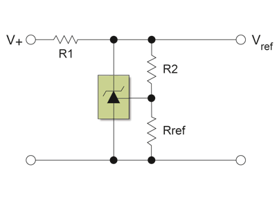
Fig. 2: Setting of reference voltage.
A single comparator is used to compare the voltage of the battery to Vref. Connected to the inverting input is the battery voltage. Hysteresis is added (see Fig. 3 ) to the set up to avoid oscillation occurring in the comparator – thus improving system performance. This is done by placing the feedback resistor Rh between the output and the non-inverting input. The 1.0 kΩ resistor R3 is used to make the ratio of R3 to Rh as simple as possible. By adjusting Rh, the bandwidth of the hysteresis loop can be changed. Increasing Rh means that the bandwidth is lowered while decreasing Rh raises the bandwidth. It is recommended that the bandwidth for the hysteresis loop should be greater than 200 mV, because when charging is terminated the voltage of the battery will drop slightly.
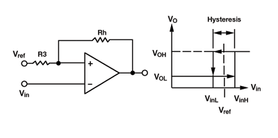
Fig. 3: Inclusion of hysteresis into charging circuit.
The equations to calculate the high and low voltages of the inverting input are as follows:


Figure 4 gives details of the full charging circuit. It contains a PNP transistor, NPN transistor, single comparator, programmable precision voltage reference and two CCRs, Q4 and Q5, placed in parallel. Q4 and Q5 are placed in parallel are used to adjust the current. It is possible to connect more than two CCRs in parallel within the charging circuit so that any required current can potentially be reached.
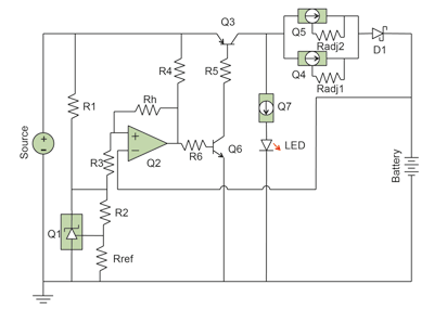
Fig. 4: Schematic of charging circuit.
The two bipolar junction transistors (BJTs), Q3 and Q6, act as a switch that controls the charging current. The base of Q6 is controlled by the output of the comparator through the 5.6kΩ resistor R6. The collector of Q6 is connected to the base of Q3 through the 1.0kΩ resistor R5. When the output of the comparator goes low, Q6 is turned off, causing Q3 to turn off, thereby resulting in termination of the charge current. To indicate that the battery is being charged, an LED is placed in series with CCR Q7 (and supplied with a constant current). This turns off when the battery has been fully charged.
In modern electronic system designs, engineers are concerned with curbing power dissipation, striving to make the products they develop more energy efficient as well as more reliable. Lowering the input voltage is one way to increase the performance of the circuit. For this reason a low VCE(sat) transistor and a low VF Schottky diode are also included in this charging circuit. The power dissipation levels are also of major importance when it comes to the operation of the CCR. It is through this device that all the voltage will be dropped, so that the battery is charged at a constant current this results in the rise in its temperature already discussed. As the device begins to heat up the current drops until it reaches a stable point. To minimize the temperature rise of the CCR, copper covers a large proportion of the empty space found on the board. The cathode of the CCR is then connected to this area of copper to provide it with a heat sink. When using multiple CCRs in parallel, it should be kept in mind that the power dissipated by the individual CCR is only the voltage multiplied by the individual current that is going through it, not the total charge current. Figure 5 describes the power dissipated by the CCRs over time.
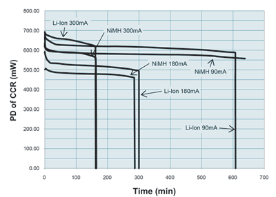
Fig. 5: Power dissipation of CCR over time.
Using the charging circuit in Fig. 4 the programmable precision reference can set a suitable Vref. The battery voltage and Vref are connected to the inputs of a comparator. While the battery voltage is less than the value of Vref, a constant current can be delivered to the battery via the CCR. Once the battery voltage is equal to Vref the charging is concluded.
ON Semiconductor’s TL431 three-terminal programmable shunt regulator and its LM311 single comparator are recommended for this circuit design. The need for inclusion of a smart IC (in the case of Li-ion battery technologies) is negated, by removing a trickle charge from the charging process. This keeps the battery in a safe operating area and helps to increase its lifespan.
The CCR-based charging circuit detailed here can, thanks to the removal of the trickle charger element, work with all of the main battery technologies (NiCd, NiMH, and Li-ion). It can thus be implemented in a multitude of different application scenarios (supporting a wide range of charging currents) – from the AAs used in the everyday domestic environment, to portable consumer devices, right through to handheld power tools. ON Semiconductor application note AND9031 provides details of the circuit in operations and results. ■
Advertisement
Learn more about ON Semiconductor


