Thermal budgeting helps select components before prototyping
A good place to start a thermal budgeting process is to understand how the IC makers determine a device’s thermal characteristics
BY ROBERT VALASCHO
Senior Field Application Engineer
Infineon Technologies North America
www.infineon.com
A power electronics engineer has to consider thermal capability of a design’s targeted components during initial selection. Yet, it is often not clear what thermal capability a component will be able to achieve when in application, since the component specification alone will not clearly define system thermal impedance. Working with the known specification, the engineer can modify generic, non-application specific data to establish true thermal budgeting for each component. As the design matures, this budget can be refined and accurately measured to guarantee thermal design before extensive and costly prototype testing. This thermal budgeting design approach is a methodology that begins with budgeting for the end application, then determining component selection, and finally working through the design process to refine the requirements of component power dissipation.
A good place to start a thermal budgeting process is to understand how the IC makers determine a device’s thermal characteristics. It is necessary to understand this process in order to translate these test results to an application. The JEDEC thermal measurement specification series JESD51 is a methodology for measuring single devices, and is the industry standard. The standard calls out measurement of the device under test on one of a set of standardized boards placed in a 305-mm3 still air box. A temperature delta is recorded with the device unbiased and again with the device biased. Based on the temperature rise realized through thermal measurement of air in the box, the thermal impedance from junction to ambient is defined by:
RthJA = temperature delta/power dissipation of device
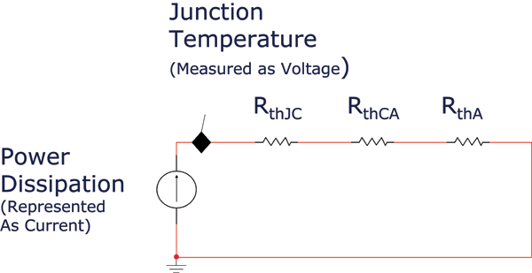
We can define three resistive components based on the IC maker’s test data; junction-to-case, case-to-air, air-to-measurement device. We can now put definition to the three components, represented in Fig. 1 .

Fig. 1: Three resistive components for thermal measurements
IC makers are kind enough to give us the first parameter, RthJC. The thermal impedance of air is negligible in comparison to the copper board and substrate. For the purpose of forming a thermal budget, we will consider RthA equals 0.
We can now determine the composition of the RthCA parameter. Let’s assume it takes a single device 1-W of power to create a 40C temperature rise and it is given in parameters that the RthJC of the device is 1 C/W. The square area of our single sided board is 40 x 40-mm with 70-µm copper thickness, which is in line with standard test boards given by JEDEC specification. Given the previously explained testing conditions, we can calculate a thermal coefficient, h, representative of the board:
(RthJA – RthJC ) [C/W] * (Power) W = (Power) W/(h W/C m2 *(Area) m2 )
39C = 1W/(h W/C m2 * 0.40 m2 )
h = 16.026 W/C m2
The coefficient h is representative of both the copper area and the thermal effects from the board substrate. Knowing this value allows us to assume that if we are successful in keeping the integrity of the board the same to our test case, then the coefficient should hold true for any size PCB given the same relative constraints. Coefficients for other JEDEC standard boards can be developed to achieve multilayer board budgeting. Specialty case boards may take testing to determine thermal resistance.
We also assume that our standardized PCB is the best possible layout for thermal efficiency. As we add in trace patterns and other components, this efficiency will decrease due to restricted heat flow through the copper traces. We also assume that component location is maximized for efficient heat spreading. So for any size board given copper thickness and layers, we have now given a best-case scenario in which we can judge thermal resistance of the system.
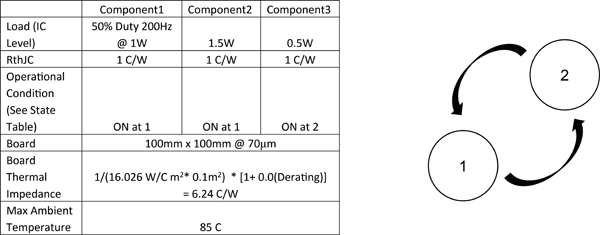
The goal of this thermal budgeting method is to determine a budget for multiple components in system application. Developing a state table (see Fig. 2 ) for use, case scenarios will be imperative in determining thermal budget. Given a set of components and functionality, it can be determined what states should be used as guidance in determining worst-case thermal efficiency. To establish a worst case budget, we need to determine both steady state and transitional operation. There are two reasons that both state characteristics are important. It is often the case where maximum temperature of the system is not the same as maximum junction temperature. When considering lifetime durability of a product, often solder and PCB substrate maximum temperature is lower than maximum IC junction temperature. So steady state thermal budgeting may have a different set of requirements. Also, when considering transitional operation and determining the peak junction temperature, we should consider this at peak steady state operating temperature of the board. Steady state information will feed into transitional operation data.
Let’s consider the following simple example where there are two operational states mutually exclusive to each other.

Fig. 2: A state table for case scenarios helps determine thermal budget
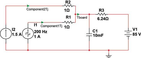
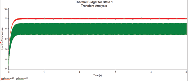
State 1 will be worst case for steady state operation. Using a simple resistor network we can determine the temperature rise. Added into the resistor network is a capacitor. Thermal capacitance is important in determining board level temperature for the transition state. The thermal capacitance will level off the measurement at “Tboard” (see Fig. 3 ). The value is more or less insignificant in thermal budgeting. It is used only as a filter to illustrate board temperature, due to a PWM signal defined in Component1 (see Fig. 4 ).

Fig. 3: Thermal capacitance levels off the measurement at Tboard

Fig. 4: Thermal budget for state 1
As mentioned, the given calculation for board thermal impedance is a best case scenario. Running a series of results that de-rate the impedance will provide a realistic approach to what is actually achievable. Through testing and experience, it is possible to de-rate the thermal resistance by adding positive margin to the resistive component. A recommendation would be to de-rate based on two methods. Often a portion of the board can be carved out as “logic” and another as “power”. Using the s area of the “power” portion will give realistic board level thermal impedance. Another option is to de-rate based on percentage, shown in Fig. 2. Applications will vary, so post-prototype testing will be necessary to feed back to the thermal budgeting model. What we can safely state is that there will not be improvement over the current budget model.
To determine max junction temperature at transition, it is now possible to replace the thermal resistance of the board with a voltage representative of the board temperature (shown in Fig. 4). This model allows us to assume our average board temperature at the IC case, at pre-state transition. Considering both state transitions, we can find that at transition Component1 = 89.62C, Component2 = 90.12C, and Component3 = 98.02C, using the models from Fig. 5 .

Fig. 5: The max junction temperature at each transition
Now we have considered the key states of operation for our simple example. We can use the results in decision making on component selection and board layout. Power dissipation chosen in this example is a factor of a planned component budget. Before even selecting a device, we can tune the power budget for each component in order to meet the temperature requirements of the system. It is possible as well to run this simulation again after actual component selection, using more complex power profiles representative of component choice.
This methodology is not meant to replace complex methods of thermal analysis. But often at product definition there is not enough information to even define such complex models with accuracy. Thermal RC calculations and finite element analysis are often saved for later in the design maturation process. As well, the budgeting process should help align attainable goals with tested results. ■
Advertisement
Learn more about Infineon Technologies


