Among the many challenges for designers of ac/dc rectifiers/converters with power factor correction (PFC) is maintaining the target performance from low-line (85-Vac) through high-line (264-Vac) conditions. Meeting this objective requires managing design trade-offs and operating compromises, selecting active and magnetic power components specified for worst-case combinations, and doing a careful physical layout. Another approach is for the OEM to “regionalize” the supply — that is, make a 110-V version for the U.S. but also a 240-V version for the United Kingdom. But this brings additional drawbacks with respect to design issues, regulatory approval, and supply chain efficiency.
The problem can also be addressed via innovative topologies and architectures, as the Adaptive Cell topology demonstrates. It overcomes traditional design limits and offers significant performance advantages, when combined with proprietary Double Clamp Zero Voltage Switching (DC-ZVS) architecture for ac/dc power conversion.
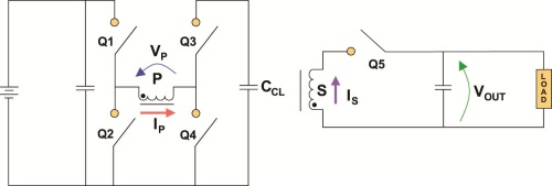
The DC-ZVS approach uses a full-bridge primary stage and a single-ended rectifier secondary stage, Fig. 1 . The inductor acts as the main energy-storage element, and has two different windings; a capacitor is the secondary storage component (hence the “double clamp”). During the three phases of what is called discontinuous-conduction-mode operation, the topology's configuration and switch timing ensure that every transition occurs at zero current, zero voltage, or both:
• During the first state, energy from the ac-line is stored in the inductor.
• During the next state, this energy is transferred to the load via the secondary stage.
• In the final state, some of the reactive energy is stored in the inductor.

Fig. 1: Simplified schematic of the DC-ZVS converter architecture shows the transition between the full-bridge primary stage and single-ended rectifier secondary stage .
This sequence minimizes switching losses even at very high frequencies. As an additional advantage, the topology also allows the use of switches with lower voltage ratings, because the transitions guarantee there will be no transient overvoltage, and the reverse voltage applied to the primary switches is limited to the peak input voltage, at most. Therefore, power designers can use devices with superior figures of merit: lower conduction losses, lower driving currents, and higher energy density.
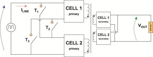
Although the DC-ZVS topology provides efficient ac/dc conversion, there is still the problem of wide input-voltage span, which is addressed at a higher functional level by the Adaptive Cell technique. This implements a dynamic approach to manage two identical DC-ZVS converters at their highest efficiency, regardless of input line-voltage variations. The converters, (see Fig. 2 ) have output stages in parallel, while their primary stages can be arranged in series or parallel. The coupled inductors share a core, and their primary-side powertrains are modulated by a common controller.

Fig. 2: Switches T1, T2, and T3 are used to dynamically configure series and parallel architecture of the Adaptive Cell approach, with sharing of the magnetic core and common modulation control.
When the input voltage is in the lower half of its range, the T1/T2/T3 switch configuration puts the primaries in parallel, thus dividing the total input current. The input current is also “shaped” according to the PFC requirements. When above the input-voltage threshold of 145 Vac, the switches connect the primaries in series, thus dividing the line voltage while the input current is shared. The result is symmetry and assurance of power sharing between the cells, under any conditions
Consequently, the two input-line ranges (low- and high-range) appear equivalent with respect to each primary stage of the two converters, Fig. 3 . The modulation control for duty-cycle range, power-factor control, voltage range, and current range can operate identically across each half of the line-input range. Even better, the cost of the three configuration switches is greatly outweighed by the reduction in size of the two-cell architecture, with both voltage range and input current requirements only half that of a single-cell architecture approach.

Fig. 3: The input-current and output-voltage waveforms for the PFM module , as the line input voltage spans the minimum-to-maximum range.
Multiple, tangible benefits
The combination of DC-ZVS topology and Adaptive Cell architecture offers numerous advantages:
• Converter efficiency is largely unaffected by input line voltage; dissipation at low line is greatly reduced; thermal dissipation is consistent even at the lower line voltages, for simplification of corner-case design as well as additional component and cooling-related savings.
• Components with higher figures of merit and reduced ratings can be used, for improved efficiency and long-term reliability.
• Zero-voltage transitions reduce the harmonic spectrum of the noise and center it on the switching frequency; plus, the higher switching frequency results in reduced, easier-to-filter noise and allows use of smaller filters.
• The symmetric line-current conduction angle encourages superior power-factor performance and recued PFC losses, even at lower line voltages.
• Optimal line-current shaping and reduced line-current dependency on instantaneous input-line voltage improves PFC and overall power quality, and reduces harmonics.
• The low voltage output meets standards for Safety Extra Low Voltage (SELV) in indirect and direct human-body contact; for the system bill of materials (BOM), there is greater availability of high-density bulk capacitors at this lower voltage level.
• Use of magnetic coupling for isolation has superior long-term reliability compared to optical isolation.
• The modules meet all applicable international EMI and EMC standards.
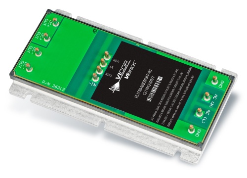
The VI BRICK PFM converter and also the comprehensive ac-front end (ACFE) module (which includes an upstream EMI filter, rectifier and transient voltage suppressor) are based on this architecture. Operating from 85 to 264 Vac, they deliver a PFC-regulated, isolated 48-Vdc output of 330 W. Power conversion density is 121 W/in.3 (7.5 W/cm3 ) for the PFM module (see Fig. 4) and 54 W/in.3 (3.3 W/cm3 ) for the complete ACFE, while efficiency is consistently high (up to 92%) over the entire input-voltage range.

Fig. 4: Vicor's VI BRICK ac-front end is the tangible implementation of the dc-ZVS approach, with associated benefits.
With the PFM and ACFE modules, a single, high-efficiency, low-profile, small-size design can be introduced quickly for worldwide markets.
Advertisement
Learn more about Vicor


