Flexible printed circuits are useful when the size and shape of your invention is integral to its overall design. You've encountered them before − in mobile phones, cameras, and other increasingly compact devices. They bend to fit into spaces otherwise impossible for traditional rigid circuit boards, and weight about 75% less. Because of the unique characteristics that set them apart, an electronics engineer must consider additional factors when designing these circuits: the degree of bending, the tightness of the bend, how the bend will be formed, and how frequently the circuit bends.
Adhere to the neutral-bend axis
The neutral-bend axis is the position on the central plane of the material stack, layers of printed circuits, insulations, and adhesives, making up the flex circuit. It is imperative to keep the neutral-bend axis as close to the center of the stack as possible in order to reduce the potential damage from tension under compression forces. This is because the amount of tension or compression placed on the outer layers correlates directly to their distance from the neutral-bend axis along with the radius of the bend.
Forming the bend angle
The bend angle dictates the amount of tension and compression imposed upon the circuit; as the angle increases so do the forces. Under no circumstances should the circuit bend more than it is designed to. Do not attempt to “break in” the circuit to remove the springiness of the material memory forcing it back into its original position, the way one bends paper back and forth to create flexibility. Instead, use a clip to keep the circuit pinned at the designated angle.
The formation of the angle is vital. Always use a forming tool to ensure that every point is equal. Doing this by hand is inaccurate and will promote circuit inconsistencies.
Use a gradual bend radius
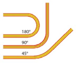
The bend radius refers to the distance measured from the inside surface of the bend to the radius of the center. When making bends you must use a larger radius in order to create a gradual increase in angle as to avoid sharp right angles caused by smaller bend radii. Obviously, tighter bends are more prone to damaging the circuit.

Image courtesy of machinedesign.com
Thickness trade-off
Everything — from the thickness of the materials, the way they are placed together, and the number of copper layers — affects the overall thickness of the circuit. Too much material will result in an overly thick circuit that is rigid and prone to damage when forcefully bent. On the other hand an overly thin circuit may reduce electrical performance. Strive for thinness while maintaining design integrity.
It is possible reduce thickness in the bend by reducing the thickness of the dielectric and adhesives as well as the base copper weight.
Static versus dynamic applications
Will your circuit be flexing regularly or is there one initial bend during installation? Circuits with a dynamic application, such as those in a flip phone per say, must be thinner than the static circuit used in building a camera which won't bend as frequently. The bend ratio associated with a dynamic application must be significantly larger as well. A balanced approach is to place the conductors in the neutral bend axis stuck between identical top and bottom layers.
Visit TechXchange to make any flex circuit related inquiries.
Story based on Machinedesign

The flexible circuit is able to wrap around the frame of the camera.
Advertisement
Learn more about Electronic Products Magazine


