By Bryon Moyer, Mouser Electronics
Ever since Wilhelm Röentgen took the first fuzzy x-ray picture in 1895 of his wife's hand, scientists have been searching for a better, non-invasive way to peer inside the human body. This search has received a lot more attention in recent years as a wave of aging baby boomers looks to technology to warn them of pending problems. They are definitely not going to be satisfied with fuzzy x-ray images.
With over 1,000 baby boomers turning 65 years old every day, the medical imaging market is also booming. According to the research firm Markets & Markets, the medical imaging market is expected to swell to $26.6 billion by 2016, driven by an aging population and advancements in the field.
Fortunately for demanding boomers, numerous technologies exist for probing into the human body, the oldest of which is the venerable x-ray. However, four more sophisticated approaches to peering into the body continue their evolution in attempts to improve precision and lower cost: computed tomography (CT), positron emission tomography (PET), magnetic resonance imaging (MRI), and ultrasound. Each of these sends a signal into the body to see how the body reacts to the signal and how that reaction affects the original signal or a return signal.
All of these techniques must discriminate small important signals from a cacophony of loud noise in the front end, which is primarily in the analog domain. High-fidelity, low-noise components, and design are critical to extracting these minute signals and delivering them as accurately as possible into the digital domain for further processing and display. Whether it is due to portability, or simply reducing the footprint, designers are demanding smaller, lower-power components. Medical imaging is one of the most demanding – and thus interesting and rewarding – fields in electronic design.
We will take a brief look at each of these four cases, examining the needs of the front-end analog subsystems.
Computed Tomography
One two-dimensional x-ray image does not tell you much, but computed tomography takes scores of them and knits them together with a computer to generate a high-resolution 3D image.
CT is one of the two technologies that utilize ionizing radiation to create a picture of what is going on inside the body. At its simplest, a CT scan is an x-ray slice of the body. Slices are repeated along the area of interest, although for performance reasons multiple slice transmitters/receivers are typically grouped next to each other. The body can also be moved during exposure in order to create a “spiral” image that can be unwound into slices or a 3D view (see Figure 1).
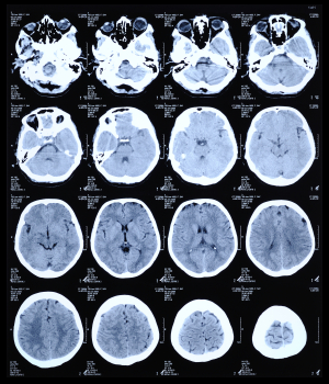
Figure 1: CT scan of the human brain.
The x-rays pass through the body and strike a crystal scintillator, which absorbs the x-ray photons and re-emits visible-light photons that are captured in a photodiode array, creating an electrical signal. The current in the diode is proportional to the impinging light, and that current is either integrated or converted to a voltage in a transimpedance amplifier (TIA).
These signals are multiplexed via FETs to the analog-to-digital converters (ADCs), after which the signal may travel a fair distance to be processed and displayed (see Figure 2). If the ADCs are fast enough they can process more signals in the interval between exposures (on the order of hundreds of microseconds or greater), meaning one can do more multiplexing and use fewer converters, helping keep size and power down. The converters must also be able to handle the high dynamic range that is typical of the detected signal. Among the ADCs that Maxim recommends are the MAX11047/8/9 (16 bits) and MAX11057/8/9 (14 bits), having 4, 6, or 8 independent channels each. They can operate at up to 250 ksps.
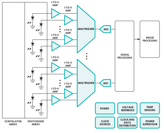
Figure 2: A typical CT front end (Courtesy of Maxim).
Computed tomography, like conventional radiography, relies on ionizing radiation, which can potentially cause genetic damage. As a result the U.S. Food and Drug Administration (FDA) enforces a set of radiological health regulations (Title 21 CFR Subchapter J) that specify exposure limits. As a result device designers are focused on faster, quieter components for better signal processing.
Positron Emission Tomography
Positron emission tomography (PET) scans also involve ionizing radiation, only this time it is gamma rays that shine from the inside out from a radioactive tracer that accumulates in an area of interest. The material emits positrons that encounter nearby electrons, releasing a burst of gamma radiation. Two high-energy photons are released heading roughly in opposite directions from each other.
The trick is to identify these specific gamma inputs from other gamma noise. So for each gamma pulse you have to see whether a matching pulse occurred at the same time on the opposite side. This takes exact sensitivity and timing.
A circular detector contains scintillators that feed photomultiplier tubes (PMTs). Each PMT will typically be fed by more than one scintillator (see Figure 3). Because the PMTs will not be exactly matched, a variable-gain amplifier (VGA) is needed to tune the signal from each one. Each VGA requires a DAC to convert the digital control signal into the appropriate voltage. The signal can then be low-pass filtered before being digitized by a 10- to 12-bit ADC sampling around 50 to 100 Msps (see Figure 4). The entire chain must be highly accurate and low-noise, while keeping power under control and components small and compact. Analog Devices recommends their AD8332 VGA as one option for trimming the PMT signals before sending them through the filter to a AD9230 12-bit ADC, which can sample at up to 250 Msps.
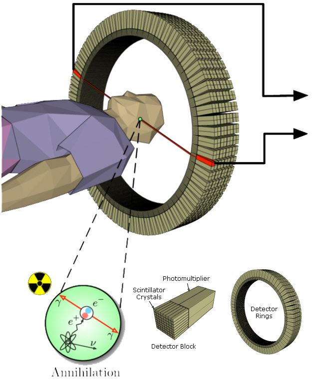
Figure 3: PET scan detector blocks and ring.
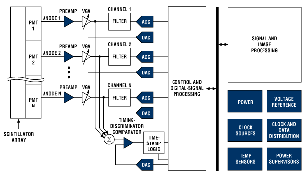
Figure 4: Block diagram for a PET system (Courtesy of Maxim).
The timing is critical. Each signal gets a timestamp, and the timestamps are compared to see if two opposing events coincide. On newer systems, the timestamp is accurate enough to locate the source of the event. Maxim has a number of comparators that can serve here, including the MAX9601; their MAX5661 16-bit DAC can be used to set the comparator reference.
Magnetic Resonance Imaging
Magnetic resonance imaging (MRI) is a completely different way of viewing inside parts of the body. It relies on the way hydrogen nuclei respond to magnetic fields. Functional MRI (fMRI) is a specialized version used in the brain, tracking oxygen instead to image blood flow based on oxygenation levels.
This process works by placing the body in a strong static magnetic field so that all the nuclei are oriented in the same direction. A varying field is then created to perturb the atoms locally; this re-orients them from their starting position. When that varying field is removed, the cell processes back to the static position. Different cells relax at different rates, ranging from tens of milliseconds to over one second, and the decay signals given off as the cells move back – in the 1 to 300 MHz range – create the image (see Figure 5). It is these differences in the relaxation timing that allow the system to discriminate different kinds of tissues.
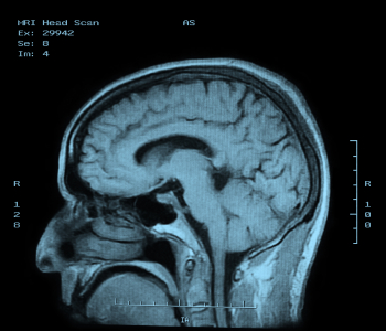
Figure 5: MRI of the brain.
A superconducting magnet, tweaked by “shim” coils, establishes the static field. Localization is handled through gradient coils that establish fields in the x, y, and z directions that vary according to position (see Figure 6). The coils for stimulating the nuclei are also used as (or placed together with) the coils that detect the response. Traditionally the excitation happens at frequencies higher than what can be handled in the front end, so the transmitted signal is up-converted to the coils and the received signal is down-converted for processing. As component performance improves, processing will be possible in the working frequency without conversion. Figure 7 shows the block diagram for an MRI system.
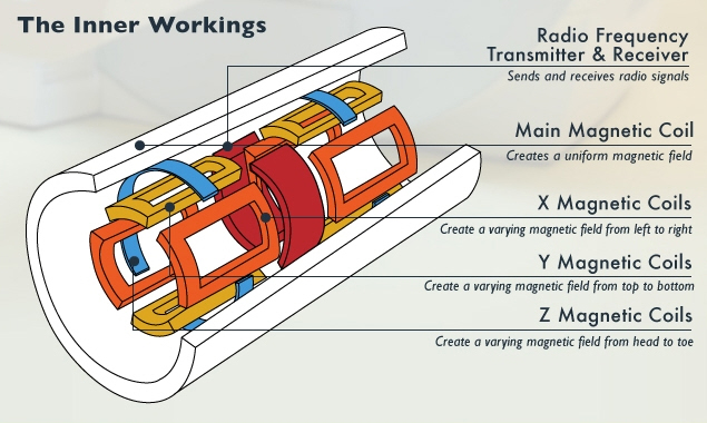
Figure 6: MRI transmitter, receiver, and coils.
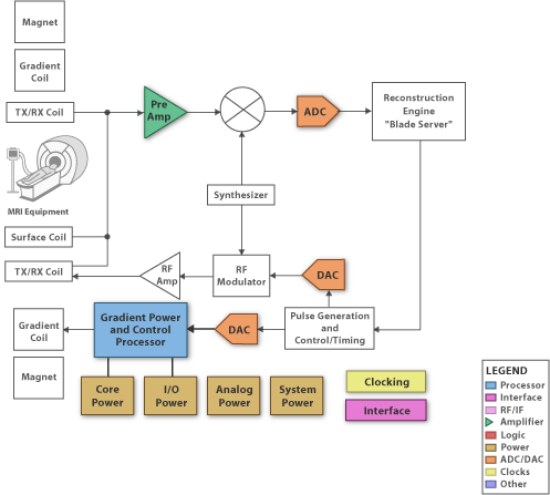
Figure 7: An MRI block diagram (Courtesy of Texas Instruments).
There are two ways to get a better signal to noise ratio (SNR) with an MRI that apply to any signal path: increase the strength of the transmitter (magnets) or increase the SNR on the receiving end. The field strength for a typical clinical MRI is 1.5 teslas. Newer “3T MRIs” can achieve 3 teslas, but they are quite noisy and – more importantly – quite expensive. It is cheaper to focus on better signal processing on the receiving side.
To transmit the signal, Analog Devices recommends their new AD9726, a 16-bit, 400 Msps RF-transmit DAC. You might think power is not an issue with all of the high-current magnets, but it is, specifically because there is so much power burned that designers want to reduce power elsewhere. MRIs are not likely to become small or low power any time soon.
Low-noise amplifiers are needed to boost the received signal prior to down-conversion; Texas Instruments (TI) includes the THS9001 in its recommendations for this role. Sampling can then happen using ADCs such as their 14-bit ADS4149, sampling up to 250 Msps. Low-noise analog front ends and fast ADCs contribute directly to the resolution of MRI imagery.
Ultrasound
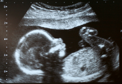
Figure 8: Ultrasound 2D image using 85 db pulses. Ultrasound is effectively a high-frequency sonar system, measuring the minute echoes of sound waves as they pass through the body. Ultrasound images (see Figure 8) resemble x-rays except that they are displayed in real-time.
The task of accurately measuring and discriminating ultrasound echoes is difficult because it is increasingly the second harmonic that is being detected rather than the fundamental. This can be done by suppressing the second harmonic in the transmit signal so that only return signals have that frequency; this requires an almost perfect 50% duty cycle on the pulse train. Alternatively, positive and inverted versions of the signal can be generated so that they can cancel out to reveal underlying harmonics. In order for this to work the rise and fall times of the pulsers must match as closely as possible so that their spectra cancel. These requirements place severe restrictions on the high-voltage pulsers. Figure 9 shows a typical ultrasound system.
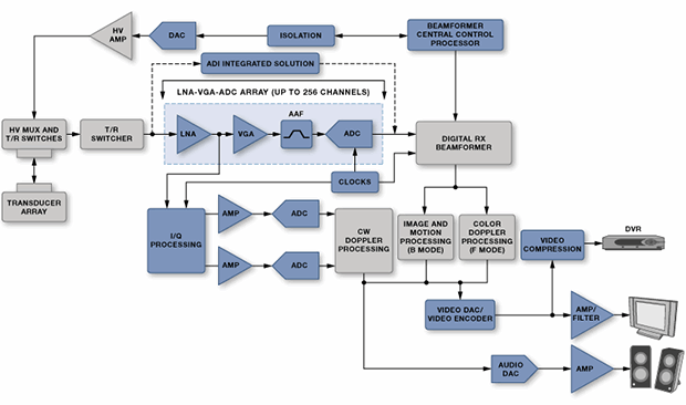
Figure 9: An ultrasound system (Courtesy of Analog Devices).
Doppler processing used to detect movement makes the design more complex yet. The whole concept relies on the transceiver side to send a high-power signal and then the receiver side to pick up a faint response. In fact, the receiving side needs to be blanked using a transmit/receive (T/R) switch when transmitting so that it is not overwhelmed – but it then has to be turned back on in time to catch the return.
The cost, power, and size requirements, especially for portable units, have driven increased integration. For example, TI's LM96570 is an eight-channel integrated beamformer, while the LM96511 integrates the LNA, VGA, and a 12-bit continuous time ΔΣ ADC into a single receive analog front end (AFE). The LM96530 is an integrated T/R switch. Maxim, meanwhile, provides the MAX2079, an eight-channel integrated receiver front end with continuous-wave (CW) doppler beamformer. The MAX4940 is a high-voltage pulsar, and the MAX4936 is their T/R switch.
Summary
There are numerous technologies being driven hard to provide more precise diagnostic images at lower cost. For systems that can be made portable – and even for big machines like MRI with high voltages and currents – low power is a must. Additionally, noise must be rejected – especially in systems like ultrasound and MRI, which by their very nature generate a lot of noise.
Medical imaging is an exciting area that is growing rapidly, thanks to a lot of smart engineers trying to stay ahead of a booming baby boomer market. Stay tuned for a lot of interesting developments.
 Bryon is a technology writer and an editor/writer for EE Journal. He has over 30 years of experience as an engineer and marketer in Silicon Valley, having worked for MMI, AMD, Cypress, Altera, Actel, Teja Technologies, and Vector Fabrics. He has focused on PLDs/FPGAs, EDA, embedded systems, multicore processing, networking protocols, software analysis, MEMS and sensors. His technical interests are broad, and he finds particular satisfaction in drawing useful parallels between seemingly unrelated fields. He has kept his technical skills high enough to facilitate cogent conversations with both users and builders. He asks stupid questions because, 90% of the time, they aren't stupid. He has a BSEE from UC Berkeley and an MSEE from Santa Clara University. Away from work, Bryon enjoys music, photography, travel, cooking, hiking, and languages.
Advertisement


