By Jack Shandle for Mouser Electronics
By the time you arrived in the office this morning you may have used RFID four times without being aware of it: when you inserted the key in your car, disabling the immobilizer circuit; when you drove through an unmanned toll booth, automatically paying your fee; when you used your cell phone to pay for your morning cappuccino; and when your ID badge registered your entry into the office. RFID may not be everywhere, but it is getting there.
The first passive transponders powered by incoming RF date back to the early 1970s, as does the vision for most of today's manifold RFID applications. Yet only with advances in semiconductor technology – not to mention Moore's Law – did RFID really start to take off.
For businesses, RFID offers an unprecedented opportunity for increasing productivity and improving customer experience by providing data at a very granular level – and by automating services such as payments and record keeping. RFID is widely used in applications as varied as livestock identification, retail inventory management, medical records management, electronic toll collection, ePassports, and more recently, mobile phones, which will be the key enabler of specific RFID technologies.
The market for RFID tags – the ID part of RFID – is growing rapidly and is expected to accelerate. IDTechEx, for example, forecasts that the number of passive RFID tags will rise from just under three billion units in 2011 to approximately 250 billion units in 2021.
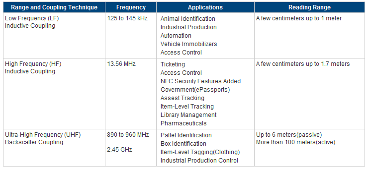
From an engineering perspective, RFID is not a single technology, and the technology varies with the frequency. Many carrier frequencies could be employed, but three predominate: LF, which uses the 125 to 135 KHz band; HF, which operates at 13.56 MHz; and, UHF, which primarily is used in the 865 to 955 MHz band. (The 2.4 GHz band may also be included in UHF.) Table 1 summarizes the applications and reading range of the three major RFID bands.
Table 1: RFID bands and applications.

Most RFID system design activity is focused on reader systems; reader design is determined primarily by the application and the characteristics of the transponders (tags) designed and manufactured by semiconductor companies. Broadly speaking, two types of tags can be used to communicate with the reader: active tags, which have an embedded battery; and passive tags, which do not. Passive tags are much more common and will be the only type discussed in this article.
Coupling Techniques
Electromagnetic coupling plays the dominant role in determining the reading range of passive tags. LF and HF RFID systems use inductive coupling: energy is transferred from the coil of the reader to the coil of the transponder (tag) over a shared magnetic field.
The reader antenna in LF and HF systems creates a strong magnetic field within an electromagnetic zone known as the near field (up to about one wavelength from the antenna). This magnetic field is strong enough to wake up the tag and supply it with the power needed to transmit its identification data to the reader. Inductive coupling can also be used to write to tags using the same energy-transfer mechanism. Figure 1 illustrates the concept of inductive coupling.

Figure 1: Inductive coupling for LF and HF systems, including NFC, takes place in the near field region.
UHF RFID systems achieve a greater read range than LF and HF systems by operating in the “far field,” which extends from approximately two wavelengths from the antenna out to infinity. Using a technique known as backscatter coupling, the electromagnetic energy of the reader's antenna is received by the tag antenna, and the RFID chip uses that energy to change the load on the antenna and reflect back an altered signal that contains the identification information.
As a practical matter, tags are designed for specific applications and vary in frequency, memory size, the standard supported, and antenna design. Texas Instruments' Tag-itTM HF-I Plus Transponder (595-RI-I03-112A-03) offers two kilobits of memory in a miniature rectangle shape and is appropriate for product authentication, asset management, and supply-chain management. It is an HF tag that operates at 13.56 MHz. At the opposite end of the memory scale NXP's HITag® μ transponder (771-HTMS1101FTBAF1) integrates 128 Kbits of memory. It is an LF tag suitable for livestock identification, laundry automation, and beer keg and gas cylinder logistics.
Design Goals
Specific RFID system reader characteristics are driven largely by the application, though several goals cross application boundaries. As in most engineering projects cost is important, which typically means minimizing the bill of materials and maximizing the added value provided by the tag manufacturer such as development tools, reference designs, and software. Mechanical design should be robust and provide vandalism protection. Consideration should be given to governmental frequency allocations in the regions where the system will be deployed. It is also important for the system to be very easy to deploy and operate, because end users are not technicians.
Near Field Communication
Power consumption is also critical, particularly in battery-powered applications such as smart phones with embedded near field communication (NFC) functionally. Although a subset of RFID technology, NFC has some distinctive enhancements:
- Shorter distance: NFC's extremely short (
- Intuitive linking procedure: NFC requires minimal effort by the end user. NFC-enabled smart phones, for example, initiate conversations with each other or with NFC readers simply by holding them in close proximity or swiping.
- Ability to communicate with unpowered RFID products: NFC works in the conventional way between self-powered devices and also supports communication with passive devices such as contactless smart cards or RF transponders.
- Synergy with Bluetooth® and Wi-Fi: In addition to its complementary relationship with RFID technology, NFC also has the built-in capability to communicate with devices that use Bluetooth and Wi-Fi wireless networks. As such, NFC provides a multi-protocol bridge between existing technologies.
According to IMS Research NFC applications will grow rapidly with mobile phones as the main driver. NFC-enabled mobile phones will jump by a factor of ten between 2012 and 2017, reaching 1.2 billion units as manufacturers adopt wireless communications and payment technology in their products as a de facto standard. This year shipments are projected to grow to 268 million units, which is up 123 percent from 120 million units in 2012. Major NFC applications include:
- Payments for entertainment tickets, taxi rides, or at any POS application. In addition, store vouchers can be stored on NFC phones.
- Authentication and access control for secure buildings using an NFC smart phone; also PC log-in, locking/unlocking car doors, etc.
- Peer-to-peer data transfer between NFC-units such as smart phones, digital cameras, and tablet computers.
- Communication links with Bluetooth or Wi-Fi for data transfer.
- Access to digital information: NFC devices will be able to read schedules from a smart poster to an NFC phone; download maps from a smart poster; and record on your cell phone where you have parked your car.
NFC Technology Basics
NFC operates in the 13.56 MHz frequency range and has a data transmission rate from 106 to 424 Kb per second. In order to maximize its usefulness, the technology is backwards compatible with the Smart Card protocols based on ISO/IEC 14443 A and ISO/IEC 14443 B, as well as with the Sony FeliCaTM card (JIS X 6319-4).
For the exchange of information between two NFC devices, a new protocol was developed which is defined in the standards ECMA-340 and ISO/IEC 18092. The NFC Forum develops specifications which ensure interoperability of NFC products. NFC has three operating modes:
- Card emulation mode (passive mode): An NFC device behaves like an existing contactless card conforming to one of the legacy standards;
- Reader/writer mode (active mode): The NFC device is active, and reads or writes to a passive legacy RFID tag;
- Peer-to-peer mode: Two NFC devices exchange information. The initiator device (polling device) requires less power compared to the reader/writer mode because the target (listener) uses its own power supply.
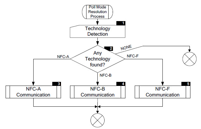
Each of the three legacy modes has its own transmission technology: NFC-A (backward compatible to ISO/IEC 14443 A); NFC-B (backward compatible to ISO/IEC 14443 B); and NFC-F (backward compatible to JIS X 6319-4).
To support legacy technologies, an NFC device has to poll the listening device (tag) to determine which protocol to use (NFC-A, NFC-B and NFC-F). Figure 2 illustrates the main flow of the polling sequence.

Figure 2: Polling flow determines the NFC communications protocol.
In NFC system design, the controller chip plays a central role. Deciding which communication mode to use is just the beginning. Among other typical MCU tasks, it has to monitor and control the transceiver, power management, and host computer interface. NFC-specific interfaces include the Secure Access Module (SAM) interface, the Subscriber Identity Module (SIM) interface, and the contactless technology (CLESS) interface.
NXP's PN544 (771-PN5441A2EC20501) is a full-featured NFC controller with an embedded 80C51 core that is appropriate for integration into mobile phones. On the reader side applications include mobile payment devices, transport and event ticketing, and object exchange (e.g., vCards and digital rights). Texas Instruments' TRF7970ARHBT (595-TRF7970ARHBT) supports the same range of applications.
Conclusion
Although RFID applications are typically not high-performance, high-speed designs, there is a good deal of complexity at the system level due to different standards, frequency options, and – most important – application requirements. Every new design brings with it decisions about security, range, directionally of the signal, environmental conditions, power consumption, memory requirements, and interface design. Once the system architecture is carefully thought out, however, the numerous design tools and development kits provided primarily by semiconductor companies provide a clear path to a successful project.
 Jack Shandle is a free-lance writer specializing in a range of electronic technologies including wireless, smart grid and semiconductors. Jack has been chief editor of several electronics publications including Electronic Design and ChipCenter. As a freelancer, he was written hundreds of articles for publications such as EE Times, EDN, CommsDesign, and TechOnline, as well as company sponsored journals such as ARM’s IQ Magazine, Xilinx’s Xcell Journal, and Mentor Graphics’ EDA Tech Forum.
Advertisement
Learn more about Electronic Products MagazineMouser Electronics


