DDR bus protocol allows signals to go idle, or tri-state, when they are not active. When debugging or performing JEDEC conformance measurements on the DDR interface, it is often necessary to perform certain measurements only on qualified portions of the signal acquired using an oscilloscope, such as during READ or WRITE bursts or on bus transactions to a specific rank.
Capturing and finding the correct sections of the waveform for analysis on the DDR interface is challenging, since it can require collecting and sorting through thousands of acquisitions for the event of interest. Defining a trigger that isolates the desired event and shows only asserted signal states greatly speeds up the debug and characterization of memory interfaces. This article looks at the use of area-based triggers for this purpose. Tektronix was the first to introduce this capability, known as Visual Trigger, as an option for its mid- and high-performance oscilloscopes last year.
An area-based trigger is a post-processing qualification operation that occurs before the waveforms are available for storage, measurements or other analysis in the oscilloscope, thus ensuring that only the waveforms of interest are retained. An area-based trigger system provides an intuitive method of triggering based on shapes created on the oscilloscope's graticule. Areas can be created in a variety of standard shapes including triangles, rectangles, hexagons, trapezoids, or user-defined shapes to fit the area to the particular trigger behavior desired. Once shapes are created on the oscilloscope's display, they can be positioned or re-sized dynamically while the oscilloscope is running. For additional insight, an area-based trigger can be combined with other oscilloscope trigger systems and can act as a Boolean logic qualifier for “A” and “B” events.
Isolating READ and WRITE Bursts on a DDR bus
DDR READ and WRITE operations are burst oriented. The burst length is programmed during initialization by writing to the appropriate bit fields in the MRS registers.
A READ or a WRITE operation begins with a READ or a WRITE command along with the column address targeted at the active open row. After a delay specified by READ/WRITE latency the data appears. There are several differences in the signaling between the two cycles that can be used to setup trigger conditions to isolate and trigger on bus events of interest, namely:
- Polarity of the DQS pre-amble
-
For DDR3 and LPDDR3, negative on READ vs. positive on WRITE
-
For DDR4, both READ and WRITE are positive
-
-
DQS and DQ phase alignment differences
-
Edge aligned for READ
-
Center aligned for WRITE
-
-
CS for qualification of bus transactions to a specific rank
-
READWRITE signal amplitude based on the oscilloscope probe point location
Isolating only READ or WRITE bursts
As seen in Fig. 1 , Channel 1 in yellow is the DQS strobe and Channel 2 in blue is the DQ data bit. A simple edge trigger has been defined for the channel connected to the DQS strobe. Without any qualification, the hardware trigger will capture both READ and WRITE bursts. Using an area-based trigger, one may isolate bursts based on pre-amble polarity and DQ/SQS phase alignment to either trigger only on READs or only on WRITEs.
Here are steps used to configure screen areas to trigger on READs, or reversed for WRITEs:
-
Areas A1 and A2 are set so that when a signal is captured there is no DQS signal in these regions. This ensures that DQS is captured coming out of tri-state.
-
Area A3 is set to filter out positive pre-amble events (WRITE), and only show negative polarity pre-amble events (READ).
-
Areas A4 and A5 are set so that DQ signal does not to enter these regions, ensuring that the DQS and DQ are aligned.
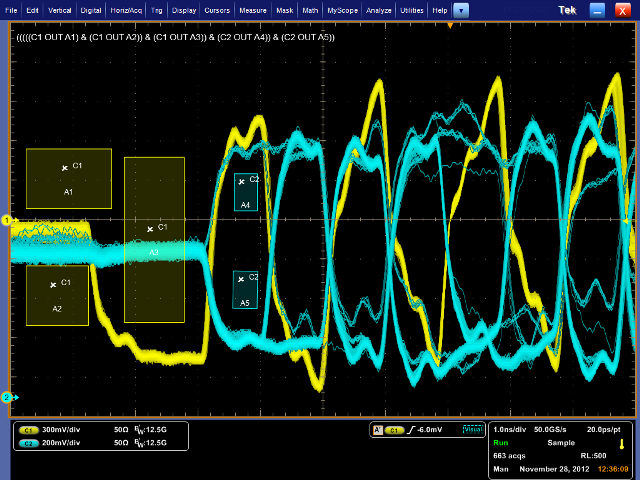
Fig. 1: Area-based triggers can be used to block out WRITEs and only trigger on READs.
Isolating a specific pattern
There are cases when it is necessary to trigger on and isolate a burst with a specific pattern such as identifying crosstalk due to capacitive coupling on adjacent lines. In Fig. 2 , an area-based trigger setup is used to isolate a WRITE burst with a DQ bit pattern of 001001X. The specific data pattern is defined using areas A4-A7 (shown in blue). In Fig. 3 , we see how a user-defined shape can be used to isolate on a DQ bit pattern.
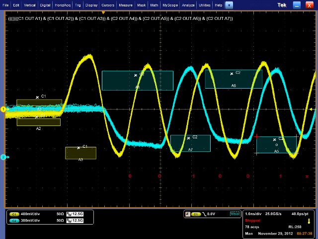
Fig. 2: This area-based trigger is setup to isolate on a DQ bit pattern of 001001X.
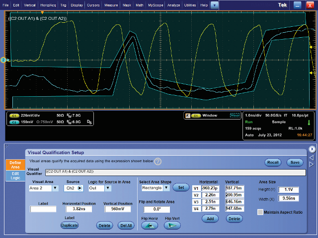
Fig. 3: This area-based trigger is based on a user defined shape setup to isolate on a DQ bit pattern.
Isolating a specific rank
An area-based trigger can be helpful in distinguishing signals from multiple ranks or slots within a DDR memory array. For an eye diagram display of a DDR3 (see Fig. 4 ), the DQS strobe signal in is shown in yellow and a DQ data signal in blue. Because the DDR3 data and strobe lines are shared by multiple components on the bus, there are two distinct amplitude levels of both the strobe and data eyes. The higher amplitudes correspond to the target rank within the memory array, while the lower amplitudes correspond to another rank.
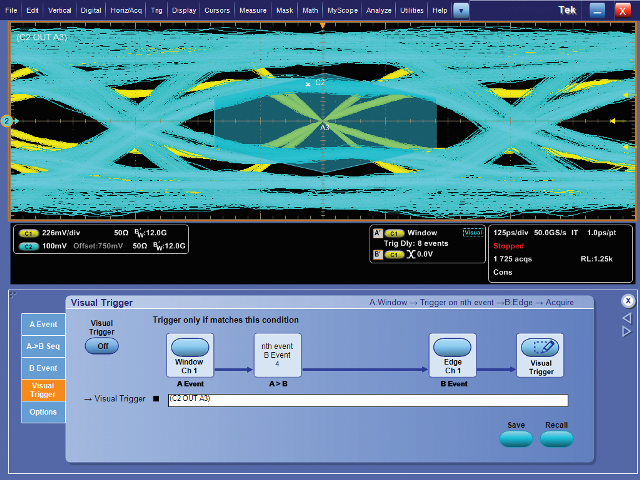
Fig. 4: DDR3 data and strobe lines are shared by multiple components on the bus, creating a need to set a trigger to only capture bits from the target rank.
In such a verification test, there is a need to acquire millions of data bits in the eye diagram, but only bits from the desired or target rank. To evaluate the eye diagrams of the target rank only, an area-based trigger can be used to capture and display only the signals from the target rank. As shown in Fig. 5 , square areas A1 and A2 are positioned to exclude the lower-amplitude strobe signals, and hexagonal area A3 is placed at the center of the eye and sized to exclude the lower-amplitude data signals. Using this trigger configuration, eye diagram analysis on the signals from the desired rank can be isolated and better targeted for analysis.
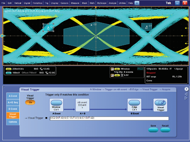
Fig. 5: Trigger areas are positioned to exclude lower-amplitude strobe signals.
Thus, area-based trigger systems provide the ability to isolate and capture events of interest in order to identify the root cause of failure on a DDR memory interface. This flexible tool can eliminate many hours involved with setting up the oscilloscope and collecting and sorting through thousands of acquisitions for the event of interest.
About the author

Prashanth Thota is a memory solutions product planner and product marketing manager at Tektronix. He has more than 12 years of experience at Tektronix and has held various positions including engineering roles designing logic analyzer products. He holds an engineering degree in electronics and communication from University of Mysore and an executive management degree from the Indian Institute of Management, Calcutta.
Advertisement
Learn more about Tektronix


