Power-over-Ethernet (PoE) has evolved over the past decade from the initial 7-W “Inline Power” standard that was introduced by Cisco in 2000, to the PoE standard (IEEE 802.3af) of 13 W in 2003, and now to the current PoE+ (IEEE 802.3at) standard of 30 W. But today’s PoE standards are quickly advancing to accommodate much higher power devices.
In 2011 Cisco introduced a new 60-W implementation it calls UPOE (see Fig. 1 ). And the IEEE is working on a new standard aimed at this higher power requirement. With its 60 W — and potential increases to 90 W — of power that can be delivered over the standard Ethernet Cat5e/Cat6 cable and RJ-45 connector scheme, 60 to 90-W PoE will make it possible to power an exceptionally wide range of products such as thin clients, IPTVs, IP turrets, remotely controlled video cameras, point-of-sale terminals, as well other devices currently requiring a separate power source.
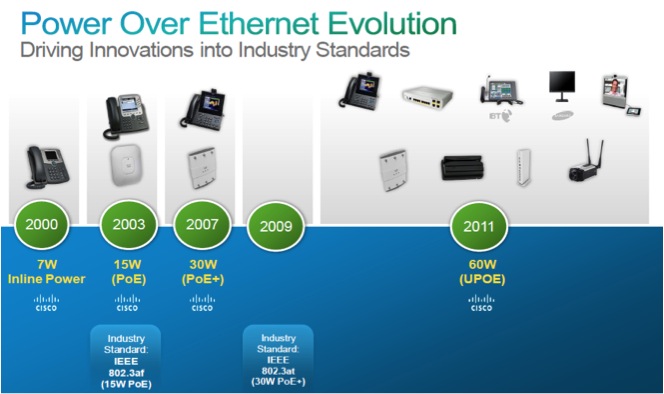
Fig. 1: The evolution of PoE has moved beyond the current 30-W standard (Cisco Systems).
Perhaps the most important benefit of the PoE evolution is the ability to intelligently manage energy consumption over the enterprise. By using energy management ICs in each powered device (PD), the power-sourcing equipment (PSE) can modulate the power delivered on a node-by-node basis, therefore enabling a far more efficient use of the PSE power supply. And as more and higher power devices are added to the PoE network, intelligent energy management will become more important.
Higher power PoE structure
The typical implementation of 15-W PoE (IEEE 802.3af) and 30-W PoE+ (IEE 802.3at) delivers power from the power sourcing equipment to the powered devices using two of the four twisted pairs in a standard Cat 5e or Cat 6 cable. Two variations of this scheme are possible. In the most common implementation scheme, power is superimposed on the signal pairs (see Fig. 2a ); in the other, the spare pairs are used to deliver power (see Fig. 2b ). In either case, the PSE provides nominal 48-Vdc common-mode power of either polarity to the PD. Each PD extracts the power using a diode bridge to deliver the power to the power conversion circuitry.
The higher-power (60 to 90-W) PoE uses all four pairs in the cable to provide power. The PSE has two separate power supplies, each capable of delivering 30 to 45 W of power to any PD node. The two parallel power sources are then applied through two diode bridges as input sources to the PD power management (see Fig. 2c ).
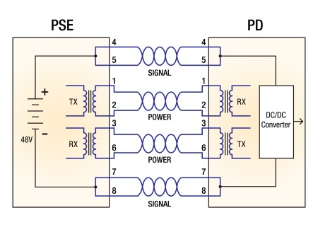
(a)
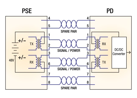
(b)
(c) 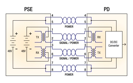
Fig. 2: Three implementations of POE are shown here. In the most common implementation scheme of 15-W PoE (IEEE 802.3af) and 30-W PoE+ (IEE 802.3at), power is superimposed on the signal pairs (a). In another, the spare pairs are used to deliver power (b). The higher-power (60 to 90-W) PoE uses all four pairs in the cable to provide power; the two parallel power sources are then applied through two diode bridges as input sources to the PD power management (c).
This power delivery system greatly expands the range of devices that can be added to the network. The PSE will now have devices that require only a few watts of power (for example, IP phones and access control nodes) and medium-power devices (for example, IP Security Cameras and wireless access points), as well as higher-power devices like IPs TVs, Point-of-Sale (POS) terminals and thin client computers. With this broad range of power requirements, it now becomes all the more important for designers to manage the PSE power output delivered to each node. Questions they need to consider include:
• What is the maximum power required at each node in the network?
• What are the power losses in the cable to each node?
• Is the PD operating on a continuous basis or can it be on standby at times?
If the PSE is required to supply the maximum power to each port on a continuous basis, the size of the PSE power supply would have to be considerably larger than needed under most operating conditions. The capability of delivering power to each PD at the level required and only when required has the dual benefit of reducing the size of the PSE power supply and allow the supply to operate at levels closer to peak efficiency.
Implementation of 60- /90-W PoE
Implementation of advanced PoE systems will require the availability of power sourcing equipment that is capable of delivering 60-W or even 90-W of power, as well as an effective technology solution for power device product manufacturers to incorporate into their new designs.
In order to achieve the requirements listed above for PoE implementation of PDs at these higher power levels, a total energy management approach is needed that not only provides high-efficiency power conversion ICs, but also focuses on total system efficiency. The objective is to dynamically control the power by monitoring the environment resulting in truly efficient system designs – not just of power sub-conversion. Additionally, a total energy management approach minimizes emissions, systematically, at the source.
60-/90-W PoE implementation at the PD needs to take into consideration a number of important factors, including:
• Multi-rail power conversion configurable to voltages required for device sub-systems including LED backlighting.
• Real-time energy monitoring — such as input power measurements, power system health monitoring on a continuous basis.
• High-efficiency conversion — including light load management, ultra-low standby power and sleep-mode power.
• Fast system dynamic response and sequencing control — including the ability to rapidly change operating mode of the device from continuous to discontinuous modes and to rapidly go in and out of standby and sleep modes; flexible sequencing control to optimize multiple-rail output power start-up.
• Digital power control — such as voltage margining to manage power consumption under differing performance requirements, managing standby and sleep requirements.
• High-efficiency EMI control and mitigation that minimizes radiative and conductive emission noise from the power supplies.
As this list suggests, intelligent energy management takes advantage of the ability of the PSE and PDs to communicate with each other to operate the network at optimum efficiency. This requires the integration of a large number of functions including power conversion, isolation, communications and control. Integrated system-on-a-chip (SoC) solutions are becoming available handle all or most of these requirements; and without an SoC solution higher-power (60 W and above) PoE PDs would require multiple components, such as two or three power management ICs, several optocouplers and custom transformers. In addition to adding component cost, consuming board space and increasing design complexity, these approaches are vulnerable to shoot-through issues and losses due to rectifier diode and reverse recovery.
For example, Akros Silicon has developed a SoC solution that can accommodate 60 W and above PoE applications using just two components: one AS1860 SoC and one external FET. Moreover, by integrating the company’s GreenEdge digital isolation technology, the AS1860 enables the implementation of many advanced diagnostic and high-voltage telemetry features that allow operators to remotely manage power, which in turn enhances reliability and energy efficiency.
PSE to PD interoperability
The IEEE has instituted a working group to establish a new PoE standard for the rapidly approaching higher-wattage implementation. In the meantime, it will be important for designers to be assured of interoperability between PSE and PD implementation. Recognizing this, Akros has entered into an interoperability collaboration with Broadcom, leading producer of PoE PSE power controllers. Broadcom’s model BCM59111 and Akros Silicon’s AS1860 (see Fig. 3 ) interoperability was demonstrated at Electronica 2012 in November 2012.
Interoperability is a key factor in achieving intelligent energy management. Communications between the PSE power management controller and each PD provides information, including instantaneous load requirements, cable losses, system status, and other operational data. The AS1860 SoC includes I/O functions, an integral A/D converter, and on-board digital isolation that combine to provide seamless data communications with the PSE.
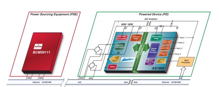
Fig. 3: Interoperability of Broadcom’s PoE PSE controller (BCM59111) and Akros’ SoC IC (AS860).
As Ethernet bandwidths continue to increase, the nature of the devices that will require PoE will also increase. With bandwidths supporting IPTVs, POS terminals and other such devices, the need to manage system power will become even more important. The power requirement for power sourcing equipment will be managed by having the ability to adjust the power delivered to the powered devices under widely varying operating conditions. The PDs will be required to provide this information in real time and respond to PSE control inputs. A total energy management approach can provide a flexible, cost-effective means of responding to the evolving — and increasing — demands of PoE systems.
Advertisement
Learn more about Akros Silicon


