By: Viral Vaidya, Business Manager
Abstract: There are many things to consider when designing a power supply for a field-programmable gate array (FPGA). These include (but are not limited to) the high number of voltage rails, and the differing requirements for both sequencing/tracking and the voltage ripple limits. This application note explains these and other power-supply considerations that an engineer must think through when designing a power supply for an FPGA.
Introduction
Field-programmable gate arrays (FPGAs) and complex programmable logic devices (CPLDs) require 3 to 15, or even more, voltage rails. The logic fabric is usually at the latest process technology node that determines the core supply voltage. Configuration, housekeeping circuitry, various I/Os, serializer/deserializer (SerDes) transceivers, clock managers, and other functions all have differing requirements for voltage rails, sequencing/tracking, and voltage ripple limits. An engineer must consider all of these issues when designing a power supply for an FPGA.
Power Requirements Start with the Voltage Rails
As programmable logic devices (PLDs) and FPGAs assume the role of a system on a chip (SoC) on your board, powering these devices is comparable to powering an entire system. High-end FPGAs such as the Xilinx® Virtex® M series and the Altera® Stratix® series easily have 10 to15 unique rails. Lower-density FPGAs such as the Xilinx Kintex® and Spartan® series or the Altera Arria® and Cyclone® series can have 2 to10 rails, depending on the application.
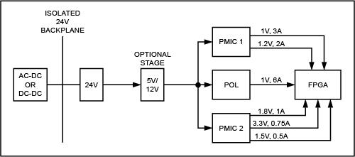
With FPGAs varying so greatly, it is critical that you choose the right power supply for each application. You must define the set of power regulators for the overall power level of each rail, the rails' sequencing requirements, and system power-management needs. Moreover, as process technology nodes become smaller in FPGAs, tighter tolerances are needed on the voltage-supply rails. This is why regulators with 1% regulation accuracy across line/load and process-voltage-temperature (PVT) variations are so critical (Figure 1).

Figure 1. A simplified block diagram shows the power architecture in industrial FPGA applications.
Understand Your System
System-level design considerations influence the choice of the power architecture. Power-system designs for simpler FPGA applications use single and multirail regulators that take a 5V/12V input and supply power to all FPGA rails, and have built-in sequencing and minimal external components. Ease of use is paramount in these applications, and high integration in the regulator will provide that ease of use. Features that simplify these power designs include internal MOSFETs, internal compensation, digital programmability, and even internal inductors.
Infrastructure equipment use FPGAs, digital-signal processors (DSPs), ASICs, and peripherals that are powered by numerous point-of-load (POL) regulators which are, in turn, controlled by a master controller. The PMBus™ protocol or I²C/SPI-based control with a microcontroller is often used in these applications. Some applications require you to control both the power of the FPGAs on the board and several other devices in a system with dynamic power management and monitoring. Sometimes it is suggested that you turn on/off some ICs based on trigger events. These are situations for advanced system power-management ICs like the MAX34440 and MAX34441, which control multiple POL regulators and fans. These devices enable dynamic power regulation with multiple operating modes like hibernate and standby, and provide superior monitoring and fault logging.
Applications that run on batteries can take advantage of the Xilinx FPGAs' power-saving modes which keep the FPGA circuits in hibernate modes except when crunching algorithms. Regulators like the MAX15053 can power these FPGAs, and can also save energy and improve efficiency with techniques such as pulse-skipping and light-load-operation mode and control.
Understand Your FPGA's Power Rails
Modern PLDs have a core supply rail that powers most of the device and consumes the highest power. With every new technology node, there is a new core supply voltage rail. Auxiliary voltage-supply rails power supporting circuits such as configuration logic, clock managers, and other housekeeping circuits. In addition, FPGAs are typically used to bridge one interface standard to another, and each I/O driver has its unique voltage rail ranging from 1.2V to 3.3V. Example interfaces include LVTTL/LVCMOS, LVDS, bus LVDS, mini-LVDS, HSTL, SSTL, and TMDS.
Special care is needed in powering high-speed SerDes transceivers, each of which can consume 1A to several amperes of current and run at speeds of 155Mbps to 28Gbps, and beyond. A 100G Ethernet application, for example, uses many such transceivers and consumes 10A or more of current. Because of the high speeds involved, a noisy power rail is particularly detrimental to their performance.
Estimate Your FPGA's Power Needs
There are three steps to take to determine your FPGA's power needs.
1. Determine the input voltage. You can use the FPGA data sheet's power estimation for this. Make sure to identify all the required voltage rails and currents.
2. Refer to the data sheets for the possible power regulators. Determine that the specifications for VIN, VOUT, IOUT, sequencing, interfaces, and programmability meet the requirements of the FPGA.
3. Use a manufacturer's product database to sort and select the best part for the FPGA and application.
Always Consider Advanced PMIC Features
Choosing the correct power supply for an FPGA or PLD is straightforward, if you assess the overall power level of each voltage rail in the application. With that understanding, you can begin the process of reviewing and eventually selecting a power supply. Power regulators today provide several advanced features beyond the basic input/output voltages and currents. Startup sequencing/tracking, startup under a prebiased load, synchronization to an external clock, or remote sensing can be integrated into a single device. Any of these new features might be critical or completely unnecessary for an application. In the end, only when you understand your application well can you really choose the right power supply.
Refer to Maxim's detailed Analog Solutions for Xilinx FPGAs and Analog Solutions for Altera FPGAs product guides.
Advertisement
Learn more about Maxim Integrated


